When I was studying CCNP back in 2009, I found a lab for MPLS that was fantastic. It showed how to buid a MPLS L3VPN network from scratch. I managed to build that in my laptop with GNS3 at that time.
Now I want to review some MPLS features so I decided to install GNS3 and build that lab again. You can find it in my github account (that was gathering dust…):
https://github.com/thomarite/mpls-basic
Install GNS3
I searched several pages to find out how to do it now a days. It seems it is mainly managed by python. This is what I had to do for Debian 10 (Testing)
sudo aptitude install dynamips
sudo pip3 install gns3-server
sudo pip3 install gns3-gui
sudo pip3 install PyQt5==5.9.2
gns3
Once I managed to run the program, I found some other issues.
First, you need to get the software to simulate the routers. I searched for recommended images for running MPLS and it seems c7200-adventerprisek9-mz.124-24.T2 was a good one. If you search for that, it will not be difficult to find somewhere to download it.
How do you install Cisco IOS images:
After that, I tested if the image worked and found another issue. I needed something called “ubridge”. You can get it here:
https://github.com/GNS3/ubridge
And finally, you needd to reboot
It took me a while but at the end I could create a lab with several routers, power them up and login to them.
As well, I modified GNS3 to use “terminator” as default terminal when connecting to the devices. That was handy.
There are many things you can configure with GNS3. Like a basic linux host to test (Alpine). I installed it as I think it will be usefull in the future:
https://docs.gns3.com/appliances/alpine-linux.html
There are many more things you can configure but for what I want, this is enough.
MPLS L3VPN
So once we have aworking GNS3 environment, we can get our hands dirty and create our MPLS L3VPN lab.
This is the diagram:
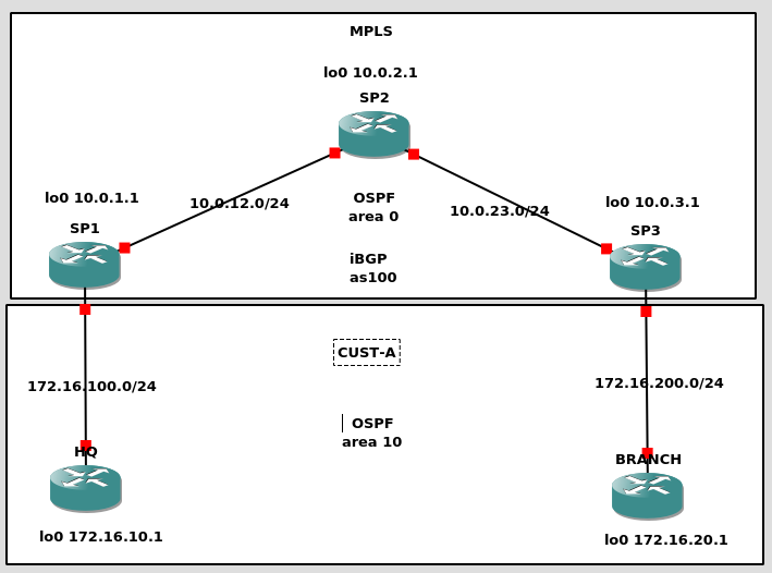
We are going to simulate a Service Provider (SP) network that is formed by SP1, SP2 and SP3. The customer network CUST-A is formed by HQ and Branch:
- SP1 and SP3 will be PE routers (they will manage the L3VPN) (PE = Provider Edge)
- SP2 will be just a P router (doesnt have visibility of any L3VPN, just handle labels) (P = Provider)
- HQ and BRANCH are CPE routers (Customer Provider Edge). They interact with PE.
The SP network uses OSPF (area0 – backbone area) as IGP to build the iBGP full mesh (as100)
CUST-A is connected to our SP network in different locations. Internally is running its own routing and both locations are in the same OSPF area 10. So the prefixes learned in HQ and Branch should be seen as Inter-Area (IA). This is quite important.
So, lets get step by step:
1- IP addressing
We need to configure the IP connectivity in all links
SP1
---
!
interface Loopback0
 ip address 10.0.1.1 255.255.255.255
!
interface GigabitEthernet1/0
 description to SP2-P
 ip address 10.0.12.1 255.255.255.0
!
interface FastEthernet0/0
 description to HQ
 ip address 172.16.100.254 255.255.255.0
!


SP2
---
!
interface Loopback0
 ip address 10.0.2.1 255.255.255.255
!
interface GigabitEthernet1/0
 description to SP1-PE
 ip address 10.0.12.2 255.255.255.0
!
interface GigabitEthernet2/0
 description to SP3-PE
 ip address 10.0.23.2 255.255.255.0
!

SP3
---
!
interface Loopback0
 ip address 10.0.3.1 255.255.255.255
!
interface GigabitEthernet1/0
 description to SP2-P
 ip address 10.0.23.1 255.255.255.0
!
interface FastEthernet0/0
 description to BRANCH
 ip address 172.16.200.254 255.255.255.0
!

HQ
---
!
interface Loopback0
 ip address 172.16.10.1 255.255.255.0
!
interface FastEthernet0/0
 description to SP1-PE
 ip address 172.16.100.1 255.255.255.0
!

BRANCH
---
!
interface Loopback0
 ip address 172.16.20.1 255.255.255.0
!
interface FastEthernet0/0
 description to SP3-PE
 ip address 172.16.200.1 255.255.255.0
!
Verify you can ping each directly connected router:
HQ#ping 172.16.100.254

Type escape sequence to abort.
Sending 5, 100-byte ICMP Echos to 172.16.100.254, timeout is 2 seconds:
!!!!!
Success rate is 100 percent (5/5), round-trip min/avg/max = 12/16/20 ms
HQ#
2- Routing in SP
We are going to configure OSPF (area 0 – backbone) as IGP in our SP network. We only want the SP loopbacks and backbone links in OSPF.
SP1
---
router ospf 1
 network 10.0.1.0 0.0.0.255 area 0
 network 10.0.12.0 0.0.0.255 area 0

SP2
---
router ospf 1
 network 10.0.2.0 0.0.0.255 area 0
 network 10.0.12.0 0.0.0.255 area 0
 network 10.0.23.0 0.0.0.255 area 0

SP3
---
router ospf 1
 network 10.0.3.0 0.0.0.255 area 0
 network 10.0.23.0 0.0.0.255 area 0
Verify that OSFP comes up in all expected links. If SP2 has two neighbors, all good:
SP2#show ip ospf neighbor

Neighbor ID     Pri   State           Dead Time   Address         Interface
10.0.3.1          1   FULL/DR         00:00:36    10.0.23.1       GigabitEthernet2/0
10.0.1.1          1   FULL/DR         00:00:34    10.0.12.1       GigabitEthernet1/0
SP2#
3- MPLS in SP
Now we are going to configure MPLS in SP. We are going to use LDP for label distribution. The configuration is pretty easy, just enable LDP using Lo0 as router ID and configure mpls only in backbone links.
SP1
---
mpls ldp router-id Loopback0 force
!
interface GigabitEthernet1/0
 description to SP2-P
 mpls ip
!

SP2
---
mpls ldp router-id Loopback0 force
!
interface GigabitEthernet1/0
 description to SP1-PE
 mpls ip
!
interface GigabitEthernet2/0
 description to SP3-PE
 mpls ip
!

SP3
---
mpls ldp router-id Loopback0 force
!
interface GigabitEthernet1/0
 description to SP2-P
 mpls ip
!
Check that LDP neighbors come up. If SP2 has two, all good.
SP2#show mpls ldp neighbor
    Peer LDP Ident: 10.0.1.1:0; Local LDP Ident 10.0.2.1:0
	TCP connection: 10.0.1.1.646 - 10.0.2.1.61226
	State: Oper; Msgs sent/rcvd: 17/18; Downstream
	Up time: 00:08:34
	LDP discovery sources:
	  GigabitEthernet1/0, Src IP addr: 10.0.12.1
        Addresses bound to peer LDP Ident:
          10.0.12.1       10.0.1.1
    Peer LDP Ident: 10.0.3.1:0; Local LDP Ident 10.0.2.1:0
	TCP connection: 10.0.3.1.31845 - 10.0.2.1.646
	State: Oper; Msgs sent/rcvd: 16/17; Downstream
	Up time: 00:08:04
	LDP discovery sources:
	  GigabitEthernet2/0, Src IP addr: 10.0.23.1
        Addresses bound to peer LDP Ident:
          10.0.23.1       10.0.3.1
SP2#
4- Configure a L3VPN – VRF
For SP, you need each customer in a VRF so you can isolate them and the customer can use any IP addressing schema. You need to make those IP prefixes unique inside SP if you want to exchange them via a routing protocol. For doing that, you need to create VPNV4 addresses that are a combination of the customer IP prefix and a RD (Router Distinguisher – 8 bytes). Each VRF has a RD and is locally significant, you could configure each PE with CUST-A using a different RD, but as best practive we keep the same RD per VRF. Having each VRF with a different RD, eachc customer cand use the same private IP prefix but to the SP eyes, after building the VPNV4, the customer prefixes will be diffierent and there will no be leaking (if you dont configure it). For exporting/importing prefixes in a VRF, we use RT (Route Target). And that is defined during the VRF creating too. Keep in mind that we only define VRFs in PE routers (SP1 and SP3). The P routers (SP2) dont need to know. In our case we are going to use RD 100:1 and RT 1:100.
SP1
---
!
ip vrf CUST-A
 rd 100:1
 route-target export 1:100
 route-target import 1:100
!

SP3
---
!
ip vrf CUST-A
 rd 100:1
 route-target export 1:100
 route-target import 1:100
!
The config above says that for each VPNv4 prefix we export from CUST-A VRF we add RT 1:100. And for any VPNv4 prefix with RT:1:00 learned by the router (more about this later in point 6) we will import it in CUST-A VRF.
Now we can configure the links to customers in their own VRF:
SP1
---
!
interface FastEthernet0/0
 description to HQ
 ip vrf forwarding CUST-A
 ip address 172.16.100.254 255.255.255.0
!

SP3
---
!
interface FastEthernet0/0
 description to BRANCH
 ip vrf forwarding CUST-A
 ip address 172.16.200.254 255.255.255.0
!
Now, let’s check if we keep the IP connectivity with CUST-A from our PE routers.
SP1#ping vrf CUST-A 172.16.100.1

Type escape sequence to abort.
Sending 5, 100-byte ICMP Echos to 172.16.100.1, timeout is 2 seconds:
!!!!!
Success rate is 100 percent (5/5), round-trip min/avg/max = 16/21/32 ms
SP1#
Keep in mind, that for CUST-A, all this is transparent.
5- Customer Routing
So now, we want our customer devices to exchange routes because they want reach each other (if not, why do you want a network 🙂 We are going to use OSPF in area 10 as routing protocol between CUST-A and SP. But SP is already using OSFP??? Yes, but keep in mind that we are using VRFs, and the OSPF implementation will be in the customer VRF. It will not interact with the SP OSPF Area 0. So we need to configure OSPF in the interfaces connecting to SP and interfaces we want to advertise (Lo0). And again, our SP2 (P) doesnt need to know anything about this.
HQ
!
router ospf 1
 log-adjacency-changes
 network 172.16.10.0 0.0.0.255 area 10
 network 172.16.100.0 0.0.0.255 area 10
!

BRANCH
!
router ospf 1
 log-adjacency-changes
 network 172.16.20.0 0.0.0.255 area 10
 network 172.16.200.0 0.0.0.255 area 10

SP1
!
router ospf 10 vrf CUST-A
 network 172.16.100.0 0.0.0.255 area 10
!

SP3
!
router ospf 10 vrf CUST-A
 network 172.16.200.0 0.0.0.255 area 10
!
Check that OSPF between CUST-A devices and SP comes up, and you are learning the CUST-A prefixes:
SP1#show ip ospf neighbor

Neighbor ID     Pri   State           Dead Time   Address         Interface
10.0.2.1          1   FULL/BDR        00:00:36    10.0.12.2       GigabitEthernet1/0
172.16.10.1       1   FULL/BDR        00:00:38    172.16.100.1    FastEthernet0/0
SP1#
SP1#show ip route vrf CUST-A

Routing Table: CUST-A
Codes: C - connected, S - static, R - RIP, M - mobile, B - BGP
       D - EIGRP, EX - EIGRP external, O - OSPF, IA - OSPF inter area
       N1 - OSPF NSSA external type 1, N2 - OSPF NSSA external type 2
       E1 - OSPF external type 1, E2 - OSPF external type 2
       i - IS-IS, su - IS-IS summary, L1 - IS-IS level-1, L2 - IS-IS level-2
       ia - IS-IS inter area, * - candidate default, U - per-user static route
       o - ODR, P - periodic downloaded static route

Gateway of last resort is not set

     172.16.0.0/16 is variably subnetted, 3 subnets, 2 masks
O       172.16.10.1/32 [110/2] via 172.16.100.1, 00:38:48, FastEthernet0/0
C       172.16.100.0/24 is directly connected, FastEthernet0/0
SP1#
In the output above, you will see that SP1 has two OSPF neighbors, one to SP2 (OSPF area 0 – backbone) and one to HQ (CUST-A VRF). As well, you will see that SP1 is learning Lo0 prefix from HQ via OSPF.
6- BGP
Now we have routing between SP1-HQ and SP3-BRANCH. But we dont have communication between HQ-BRANCH yet. And this is the goal at the end of the day.
So now, we need our PE routers to exchange the customer prefixes. We are going to use BGP/MP-BGP.
As we are in the same AS100 (Autonomous System) we are going to use iBGP (internal BGP). Following best practices, we are going to build our full mesh iBGP on loopbacks. iBGP relays on a IGP, and that is already configured via OSPF in our network.
SP1
!
router bgp 100
 neighbor 10.0.3.1 remote-as 100
 neighbor 10.0.3.1 update-source Loopback0

SP3
!
router bgp 100
 neighbor 10.0.1.1 remote-as 100
 neighbor 10.0.1.1 update-source Loopback0
Check that BGP comes up between SP1-SP3
SP1#show ip bgp summary
BGP router identifier 10.0.1.1, local AS number 100
BGP table version is 1, main routing table version 1

Neighbor        V          AS MsgRcvd MsgSent   TblVer  InQ OutQ Up/Down  State/PfxRcd
10.0.3.1        4        100      53      53        1    0    0 00:50:08        0
SP1#
So we have BGP between our PE routers. Now we need to configure the exchange of those VPNv4 routes so CUST-A devices can learn prefixes from its own network.
SP1
!
router bgp 100
 address-family vpnv4
  neighbor 10.0.3.1 activate
  neighbor 10.0.3.1 send-community both
 exit-address-family

SP3
!
router bgp 100
 address-family vpnv4
  neighbor 10.0.1.1 activate
  neighbor 10.0.1.1 send-community both
 exit-address-family
The above part is the MP-BGP part (MultiProtocol-BGP). Inside our BGP connection between SP1-SP3 we have enabled a type of exchange of prefixes for vpnv4.
But, we dont have VPNv4 prefixes yet.
SP1#show ip bgp vpnv4 all
BGP table version is 7, local router ID is 10.0.1.1
Status codes: s suppressed, d damped, h history, * valid, > best, i - internal,
              r RIB-failure, S Stale
Origin codes: i - IGP, e - EGP, ? - incomplete

   Network          Next Hop            Metric LocPrf Weight Path
SP1#
Because they need to be in the BGP table first. We have routing between PE-CE (ospf area 10) but we dont have any kind of redistribution between OSPF-BGP. Let’s do that:
SP1
!
router ospf 10 vrf CUST-A
 redistribute bgp 100 subnets
!
router bgp 100
 address-family ipv4 vrf CUST-A
  redistribute ospf 10 vrf CUST-A
 exit-address-family
!

SP3
!
router ospf 10 vrf CUST-A
 redistribute bgp 100 subnets
!
router bgp 100
 address-family ipv4 vrf CUST-A
  redistribute ospf 10 vrf CUST-A
 exit-address-family
!
Let’s check again our VPNv4 table:
SP1#show ip bgp vpnv4 all
BGP table version is 9, local router ID is 10.0.1.1
Status codes: s suppressed, d damped, h history, * valid, > best, i - internal,
              r RIB-failure, S Stale
Origin codes: i - IGP, e - EGP, ? - incomplete

   Network          Next Hop            Metric LocPrf Weight Path
Route Distinguisher: 100:1 (default for vrf CUST-A)
*> 172.16.10.1/32   172.16.100.1             2         32768 ?
*>i172.16.20.1/32   10.0.3.1                 2    100      0 ?
*> 172.16.100.0/24  0.0.0.0                  0         32768 ?
*>i172.16.200.0/24  10.0.3.1                 0    100      0 ?
SP1#
So now, we can see in SP1 the prefixes from HQ and BRANCH routers!
Now, let’s check the CUST-A routing table from SP1 and HQ:
SP1#show ip route vrf CUST-A

Routing Table: CUST-A
Codes: C - connected, S - static, R - RIP, M - mobile, B - BGP
       D - EIGRP, EX - EIGRP external, O - OSPF, IA - OSPF inter area
       N1 - OSPF NSSA external type 1, N2 - OSPF NSSA external type 2
       E1 - OSPF external type 1, E2 - OSPF external type 2
       i - IS-IS, su - IS-IS summary, L1 - IS-IS level-1, L2 - IS-IS level-2
       ia - IS-IS inter area, * - candidate default, U - per-user static route
       o - ODR, P - periodic downloaded static route

Gateway of last resort is not set

     172.16.0.0/16 is variably subnetted, 4 subnets, 2 masks
B       172.16.200.0/24 [200/0] via 10.0.3.1, 01:08:19
B       172.16.20.1/32 [200/2] via 10.0.3.1, 00:01:33
O       172.16.10.1/32 [110/2] via 172.16.100.1, 01:15:49, FastEthernet0/0
C       172.16.100.0/24 is directly connected, FastEthernet0/0
SP1#


HQ#show ip route
Codes: C - connected, S - static, R - RIP, M - mobile, B - BGP
       D - EIGRP, EX - EIGRP external, O - OSPF, IA - OSPF inter area
       N1 - OSPF NSSA external type 1, N2 - OSPF NSSA external type 2
       E1 - OSPF external type 1, E2 - OSPF external type 2
       i - IS-IS, su - IS-IS summary, L1 - IS-IS level-1, L2 - IS-IS level-2
       ia - IS-IS inter area, * - candidate default, U - per-user static route
       o - ODR, P - periodic downloaded static route

Gateway of last resort is not set

     172.16.0.0/16 is variably subnetted, 4 subnets, 2 masks
O IA    172.16.200.0/24 [110/2] via 172.16.100.254, 01:07:09, FastEthernet0/0
O IA    172.16.20.1/32 [110/3] via 172.16.100.254, 00:00:22, FastEthernet0/0
C       172.16.10.0/24 is directly connected, Loopback0
C       172.16.100.0/24 is directly connected, FastEthernet0/0
HQ#
HQ#
So from SP1, we can see that is learning BRANCH 172.16.200.0/24 and 172.16.20.1/32 via iBGP (from SP3 loopback 10.0.3.1). The 172.16.10.1/32 (HQ loopback) via OSPF.
From HQ, we see it is learning BRANCH Prefixes too and they come up as O IA. This is very important, and it is material for another post about OSPF Down-Bit.
7- Conclusion
We have IP connectivity between our CUST-A devices across a MPLS L3VPN
HQ#ping 172.16.20.1

Type escape sequence to abort.
Sending 5, 100-byte ICMP Echos to 172.16.20.1, timeout is 2 seconds:
!!!!!
Success rate is 100 percent (5/5), round-trip min/avg/max = 44/76/156 ms
HQ#
HQ#traceroute 172.16.20.1

Type escape sequence to abort.
Tracing the route to 172.16.20.1

  1 172.16.100.254 16 msec 8 msec 12 msec
  2 10.0.12.2 [MPLS: Labels 17/20 Exp 0] 72 msec 40 msec 60 msec
  3 172.16.200.254 [MPLS: Label 20 Exp 0] 52 msec 8 msec 60 msec
  4 172.16.200.1 40 msec 52 msec 40 msec
HQ#
We have built a MPLS L3VPN from the bottom up. There are many points that can be explained with much more detail but that wasnt the goal. Just wanted to build this MPLS network so I can do some hands-on troubleshooting and review a couple of concepts.
Ideally, at some point, I would like to build a MPLS Segment Routing GNS3 networks.
More to come hopefully.