I read once about how to do load-balancing when using Route-Reflectors (RR) in a MPLS L3VPN network. It is a insteresting topic because RRs only reflect the best prefixes to the its clients. So how we make the RR to send more than one?
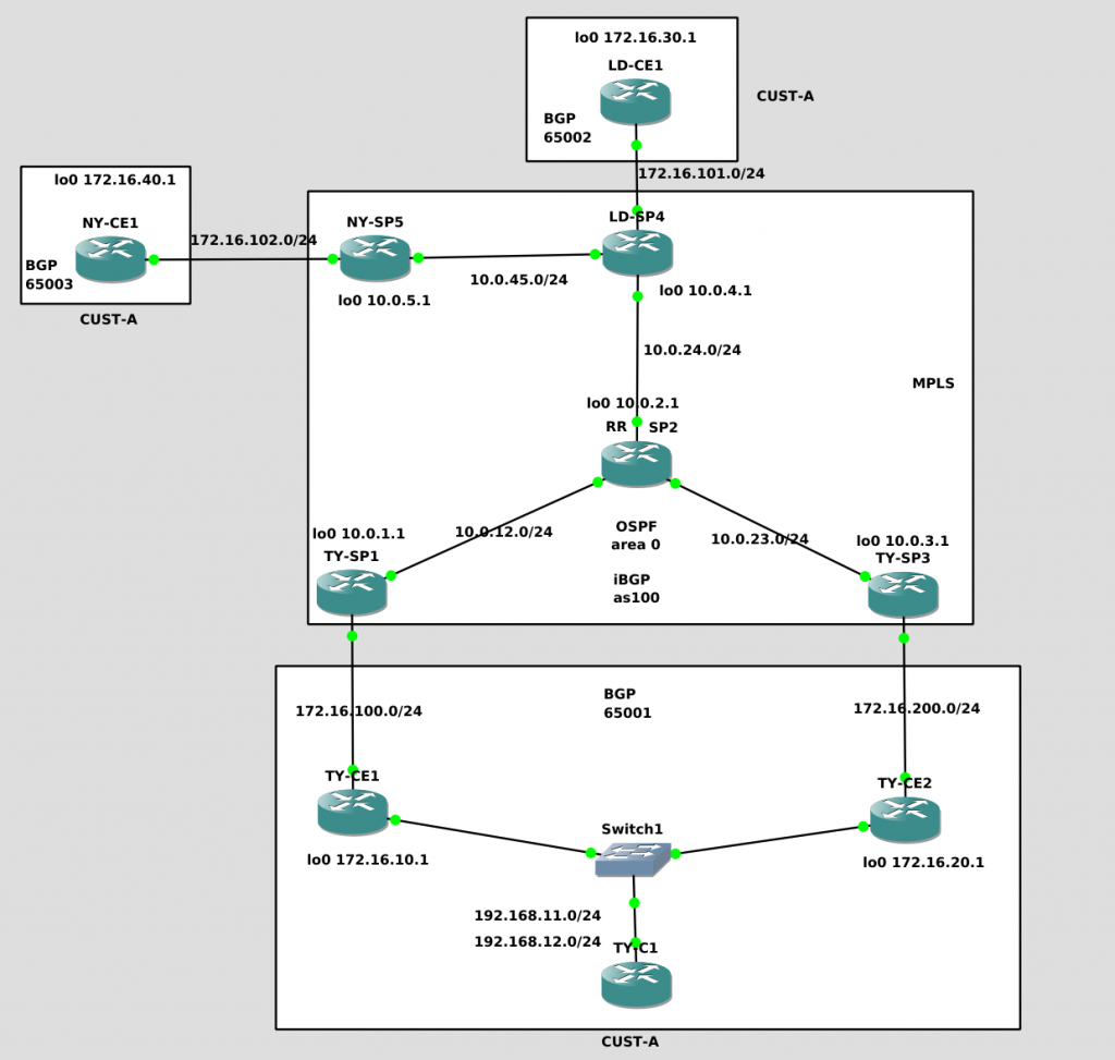
We have one customer vrf “CUST-A” with three locations: TY, LD and NY.
We are using BGP for PE-CE routing. Each site will use a different private ASN. Our SP is ASN 100.
TY has two connection to our SP so we want to make use of both of them.
We have a RR SP2 that is in line. So we need a full-mesh iBGP from all PE to SP2.
Our SP IGP is OSFP.
The goal is to make all other PE connected to CUST-A sites to be able to load-balance to TY site prefixes 192.168.11.0/24 and 192.168.12.0/24 using TY-SP1 and TY-SP3.
We start building the whole network as standard. This is very similar as stated in our first lab:
This is RR SP2 config:
!
ip vrf CUST-A
 rd 100:1
 route-target export 1:100
 route-target import 1:100
!
interface Loopback0
 ip address 10.0.2.1 255.255.255.255
!
interface GigabitEthernet1/0
 description to SP1-PE
 ip address 10.0.12.2 255.255.255.0
 negotiation auto
 mpls ip
!
interface GigabitEthernet2/0
 description to SP3-PE
 ip address 10.0.23.2 255.255.255.0
 negotiation auto
 mpls ip
!
interface FastEthernet3/0
 description TO-LD-SP4
 ip address 10.0.24.2 255.255.255.0
 duplex auto
 speed auto
 mpls ip
!
router ospf 1
 log-adjacency-changes
 network 10.0.2.0 0.0.0.255 area 0
 network 10.0.12.0 0.0.0.255 area 0
 network 10.0.23.0 0.0.0.255 area 0
 network 10.0.24.0 0.0.0.255 area 0
!
router bgp 100
 no synchronization
 bgp log-neighbor-changes
 neighbor 10.0.1.1 remote-as 100
 neighbor 10.0.1.1 update-source Loopback0
 neighbor 10.0.1.1 route-reflector-client
 neighbor 10.0.3.1 remote-as 100
 neighbor 10.0.3.1 update-source Loopback0
 neighbor 10.0.3.1 route-reflector-client
 neighbor 10.0.4.1 remote-as 100
 neighbor 10.0.4.1 update-source Loopback0
 neighbor 10.0.4.1 route-reflector-client
 neighbor 10.0.5.1 remote-as 100
 neighbor 10.0.5.1 update-source Loopback0
 neighbor 10.0.5.1 route-reflector-client
 no auto-summary
 !
 address-family vpnv4
  neighbor 10.0.1.1 activate
  neighbor 10.0.1.1 send-community both
  neighbor 10.0.1.1 route-reflector-client
  neighbor 10.0.3.1 activate
  neighbor 10.0.3.1 send-community both
  neighbor 10.0.3.1 route-reflector-client
  neighbor 10.0.4.1 activate
  neighbor 10.0.4.1 send-community both
  neighbor 10.0.4.1 route-reflector-client
  neighbor 10.0.5.1 activate
  neighbor 10.0.5.1 send-community both
  neighbor 10.0.5.1 route-reflector-client
 exit-address-family
 !
 address-family ipv4 vrf CUST-A
  no synchronization
 exit-address-family
!
!
mpls ldp router-id Loopback0 force
The configs for the SP PE follow the same patern, this is TY-SP1:
!
ip vrf CUST-A
 rd 100:1
 route-target export 1:100
 route-target import 1:100
!
interface Loopback0
 ip address 10.0.1.1 255.255.255.255
!
interface FastEthernet0/0
 description to HQ
 ip vrf forwarding CUST-A
 ip address 172.16.100.254 255.255.255.0
 duplex half
!
interface GigabitEthernet1/0
 description to SP2-P
 ip address 10.0.12.1 255.255.255.0
 negotiation auto
 mpls ip
!
router ospf 1
 log-adjacency-changes
 network 10.0.1.0 0.0.0.255 area 0
 network 10.0.12.0 0.0.0.255 area 0
!
router bgp 100
 no synchronization
 bgp log-neighbor-changes
 neighbor 10.0.2.1 remote-as 100
 neighbor 10.0.2.1 update-source Loopback0
 no auto-summary
 !
 address-family vpnv4
  neighbor 10.0.2.1 activate
  neighbor 10.0.2.1 send-community both
 exit-address-family
 !
 address-family ipv4 vrf CUST-A
  neighbor 172.16.100.1 remote-as 65001
  neighbor 172.16.100.1 activate
  neighbor 172.16.100.1 soft-reconfiguration inbound
  no synchronization
 exit-address-family
!
mpls ldp router-id Loopback0 force
!
Let’ see if LD-CE1 can ping our TY-C1
LD-CE1#traceroute 192.168.12.1 source 172.16.30.1

Type escape sequence to abort.
Tracing the route to 192.168.12.1

  1 172.16.101.254 8 msec 20 msec 8 msec
  2 10.0.24.2 [MPLS: Labels 18/23 Exp 0] 40 msec 40 msec 36 msec
  3 172.16.200.254 [MPLS: Label 23 Exp 0] 12 msec 32 msec 28 msec
  4 172.16.200.1 60 msec 40 msec 40 msec
  5 192.168.12.1 [AS 65001] 40 msec 60 msec 60 msec
LD-CE1#
LD-CE1#
LD-CE1#ping 192.168.11.1 source 172.16.30.1

Type escape sequence to abort.
Sending 5, 100-byte ICMP Echos to 192.168.11.1, timeout is 2 seconds:
Packet sent with a source address of 172.16.30.1
!!!!!
Success rate is 100 percent (5/5), round-trip min/avg/max = 44/54/72 ms
LD-CE1#
LD-CE1#
LD-CE1#
LD-CE1#sh
LD-CE1#show ip rou
LD-CE1#show ip route
Codes: C - connected, S - static, R - RIP, M - mobile, B - BGP
       D - EIGRP, EX - EIGRP external, O - OSPF, IA - OSPF inter area
       N1 - OSPF NSSA external type 1, N2 - OSPF NSSA external type 2
       E1 - OSPF external type 1, E2 - OSPF external type 2
       i - IS-IS, su - IS-IS summary, L1 - IS-IS level-1, L2 - IS-IS level-2
       ia - IS-IS inter area, * - candidate default, U - per-user static route
       o - ODR, P - periodic downloaded static route

Gateway of last resort is not set

B    192.168.12.0/24 [20/0] via 172.16.101.254, 01:19:31
     172.16.0.0/16 is variably subnetted, 2 subnets, 2 masks
C       172.16.30.1/32 is directly connected, Loopback0
C       172.16.101.0/24 is directly connected, FastEthernet0/0
B    192.168.11.0/24 [20/0] via 172.16.101.254, 01:19:31
LD-CE1#
So, what do we see when everything is configured?
From SP2-RR, we see all BGP peers up to PEs and in the vpnv4 table we can see the TY prefixes 192.168.11.0/24 and 192.168.12.0/24. But only the path from TY-SP1 is preferred….
SP2#show ip ospf neighbor

Neighbor ID     Pri   State           Dead Time   Address         Interface
10.0.4.1          1   FULL/DR         00:00:39    10.0.24.1       FastEthernet3/0
10.0.3.1          1   FULL/DR         00:00:39    10.0.23.1       GigabitEthernet2/0
10.0.1.1          1   FULL/BDR        00:00:37    10.0.12.1       GigabitEthernet1/0
SP2#
SP2#
SP2#show ip bgp summary
BGP router identifier 10.0.2.1, local AS number 100
BGP table version is 1, main routing table version 1

Neighbor        V          AS MsgRcvd MsgSent   TblVer  InQ OutQ Up/Down  State/PfxRcd
10.0.1.1        4        100      98     111        1    0    0 01:25:16        0
10.0.3.1        4        100      93     108        1    0    0 01:25:05        0
10.0.4.1        4        100      96     114        1    0    0 00:55:06        0
10.0.5.1        4        100      29      32        1    0    0 00:28:02        0
SP2#
SP2#show ip bgp vpnv4 all
BGP table version is 9, local router ID is 10.0.2.1
Status codes: s suppressed, d damped, h history, * valid, > best, i - internal,
              r RIB-failure, S Stale
Origin codes: i - IGP, e - EGP, ? - incomplete

   Network          Next Hop            Metric LocPrf Weight Path
Route Distinguisher: 100:1 (default for vrf CUST-A)
*>i172.16.30.1/32   10.0.4.1                 0    100      0 65002 i
*>i192.168.11.0     10.0.1.1                 0    100      0 65001 i
* i                 10.0.3.1                 0    100      0 65001 i
*>i192.168.12.0     10.0.1.1                 0    100      0 65001 i
* i                 10.0.3.1                 0    100      0 65001 i
SP2#
Let confirm that the PE only receive the best prefix from the RR. So, from LD-SP4, we can see the paths to TY 192.168.11/12 via TY-SP1 only:
LD-SP4#show ip bgp vpnv4 all
BGP table version is 18, local router ID is 10.0.4.1
Status codes: s suppressed, d damped, h history, * valid, > best, i - internal,
              r RIB-failure, S Stale
Origin codes: i - IGP, e - EGP, ? - incomplete

   Network          Next Hop            Metric LocPrf Weight Path
Route Distinguisher: 100:1 (default for vrf CUST-A)
*> 172.16.30.1/32   172.16.101.1             0             0 65002 i
*>i192.168.11.0     10.0.1.1                 0    100      0 65001 i
*>i192.168.12.0     10.0.1.1                 0    100      0 65001 i
LD-SP4#
How do we make RR-SP2 to learn and advertise TY-SP1 and TY-SP3 paths. We need to use different RD in TY-SP1/3 respectively.
We have RD 100:1 assigned to CUST-A in all PEs. We are going to change that in TY-SP1/3 so RR will see two different VPNv4 prefixes for the same destination.
Let’s change TY-SP1 RD 100:1 to 100:101 and TY-SP3 to 100:102. Watch out as all routing config related to VRF CUST-A will disappear.
And what about the RT config? Do we have to change anything? Actually, we need to keep it the same (we need to retype it), nothing changes here. Keep in mind that RT is used to import/export vpnv4 prefixes into the VRF. The RD is not used to import/export so for that reason (as we are going to see) we could actually use any RD for a VRF in a PE.
Let’s see the changes for TY-SP1:
TY-SP1(config)#ip vrf CUST-A
TY-SP1(config-vrf)#no rd 100:1
% "rd 100:1" for VRF CUST-A scheduled for deletion
TY-SP1(config-vrf)#
*Apr 27 22:28:48.347: %BGP-5-ADJCHANGE: neighbor 172.16.100.1 vpn vrf CUST-A Down Neighbor deleted
TY-SP1(config-vrf)#rd 100:101
% Deletion of "rd" in progress; wait for it to complete
TY-SP1(config-vrf)#
TY-SP1(config-vrf)#rd 100:101
TY-SP1(config-vrf)#route-target export 100:1
TY-SP1(config-vrf)#route-target import 100:1
TY-SP1(config-vrf)#exit
TY-SP1(config)#router bgp 100
TY-SP1(config-router)#address-family ipv4 vrf CUST-A
TY-SP1(config-router-af)#  neighbor 172.16.100.1 remote-as 65001
TY-SP1(config-router-af)#  neighbor 172.16.100.1 activate
TY-SP1(config-router-af)#  neighbor 172.16.100.1 soft-reconfiguration inbound
TY-SP1(config-router-af)#
*Apr 27 22:33:50.571: %BGP-5-ADJCHANGE: neighbor 172.16.100.1 vpn vrf CUST-A Up
TY-SP1(config-router-af)#
So after repeating the same step in TY-SP3 (using RD 100:102), let’s see what happens in RR-SP2:
SP2#show ip bgp vpnv4 all
BGP table version is 51, local router ID is 10.0.2.1
Status codes: s suppressed, d damped, h history, * valid, > best, i - internal,
              r RIB-failure, S Stale
Origin codes: i - IGP, e - EGP, ? - incomplete

   Network          Next Hop            Metric LocPrf Weight Path
Route Distinguisher: 100:1 (default for vrf CUST-A)
*>i172.16.30.1/32   10.0.4.1                 0    100      0 65002 i
* i192.168.11.0     10.0.3.1                 0    100      0 65001 i
*>i                 10.0.1.1                 0    100      0 65001 i
* i192.168.12.0     10.0.3.1                 0    100      0 65001 i
*>i                 10.0.1.1                 0    100      0 65001 i
Route Distinguisher: 100:101
*>i192.168.11.0     10.0.1.1                 0    100      0 65001 i
*>i192.168.12.0     10.0.1.1                 0    100      0 65001 i
Route Distinguisher: 100:102
*>i192.168.11.0     10.0.3.1                 0    100      0 65001 i
*>i192.168.12.0     10.0.3.1                 0    100      0 65001 i
SP2#
Now we can see VPNv4 for 100:101 (TY-SP1) and 100:102 (TY-SP2)!!!
Ok, let’s what the other PE are seeing. In our case, let’s check LD-SP4:
LD-SP4#show ip bgp vpnv4 all
BGP table version is 18, local router ID is 10.0.4.1
Status codes: s suppressed, d damped, h history, * valid, > best, i - internal,
              r RIB-failure, S Stale
Origin codes: i - IGP, e - EGP, ? - incomplete

   Network          Next Hop            Metric LocPrf Weight Path
Route Distinguisher: 100:1 (default for vrf CUST-A)
*> 172.16.30.1/32   172.16.101.1             0             0 65002 i
* i192.168.11.0     10.0.3.1                 0    100      0 65001 i
*>i                 10.0.1.1                 0    100      0 65001 i
* i192.168.12.0     10.0.3.1                 0    100      0 65001 i
*>i                 10.0.1.1                 0    100      0 65001 i
Route Distinguisher: 100:101
*>i192.168.11.0     10.0.1.1                 0    100      0 65001 i
*>i192.168.12.0     10.0.1.1                 0    100      0 65001 i
Route Distinguisher: 100:102
*>i192.168.11.0     10.0.3.1                 0    100      0 65001 i
*>i192.168.12.0     10.0.3.1                 0    100      0 65001 i
LD-SP4#
LD-SP4#
LD-SP4#show ip route vrf CUST-A

Routing Table: CUST-A
Codes: C - connected, S - static, R - RIP, M - mobile, B - BGP
       D - EIGRP, EX - EIGRP external, O - OSPF, IA - OSPF inter area
       N1 - OSPF NSSA external type 1, N2 - OSPF NSSA external type 2
       E1 - OSPF external type 1, E2 - OSPF external type 2
       i - IS-IS, su - IS-IS summary, L1 - IS-IS level-1, L2 - IS-IS level-2
       ia - IS-IS inter area, * - candidate default, U - per-user static route
       o - ODR, P - periodic downloaded static route

Gateway of last resort is not set

B    192.168.12.0/24 [200/0] via 10.0.1.1, 00:01:05
     172.16.0.0/16 is variably subnetted, 2 subnets, 2 masks
B       172.16.30.1/32 [20/0] via 172.16.101.1, 00:33:47
C       172.16.101.0/24 is directly connected, FastEthernet0/0
B    192.168.11.0/24 [200/0] via 10.0.1.1, 00:01:05
LD-SP4#
So, LD-SP4 is receiving the VPNv4 100:101 and 100:102 from RR-SP2!!! That’s good, but we are still seeing the path to TY 192.168.11/12 prefixes via TY-SP1 (10.0.1.1) only.
So why BGP ECMP is not working? Because we have to enable it.
LD-SP4(config)#router bgp 100
LD-SP4(config-router)#address-family ipv4 vrf CUST-A
LD-SP4(config-router-af)#maximum-paths eibgp 2
LD-SP4(config-router-af)#
*Apr 27 22:58:25.447: BGP: VPNv4 Unicast multipath configuration changed
*Apr 27 22:58:25.447: BGP-VPN(4):  MPLS label changed for prefix 100:1:192.168.11.0/24
*Apr 27 22:58:25.447: BGP-VPN(4): multipath from neighbor 10.0.2.1 nexthop 10.0.3.1 new outlabel 24
*Apr 27 22:58:25.447: vpn: free local label 1048577 for remote prefix CUST-A:192.168.11.0/24
*Apr 27 22:58:25.447: vpn: get path labels: 100:1:192.168.11.0/255.255.255.0
*Apr 27 22:58:25.451: vpn(4): inlabel=nolabel, outlabel=22, outlabel owner=BGP
*Apr 27 22:58:25.451: vpn(4): Announce labels to IPRM CUST-A:192.168.11.0/24 gw 10.0.1.1 inlabel=nolabel, outlabel=22
*Apr 27 22:58:25.451: BGP-VPN(4):  MPLS label changed for prefix 100:1:192.168.12.0/24
*Apr 27 22:58:25.451: BGP-VPN(4): multipath from neighbor 10.0.2.1 nexthop 10.0.3.1 new outlabel 23
*Apr 27 22:58:25.451: vpn: free local label 1048577 for remote prefix CUST-A:192.168.12.0/24
*Apr 27 22:58:25.451: vpn: get path labels: 100:1:192.168.12.0/255.255.255.0
*
LD-SP4(config-router-af)#endApr 27 22:58:25.451: vpn(4): inlabel=nolabel, outlabel=21, outlabel owner=BGP
*Apr 27 22:58:25.451: vpn(4): Announce labels to IPRM CUST-A:192.168.12.0/24 gw 10.0.1.1 inlabel=nolabel, outlabel=21
*Apr 27 22:58:25.455: vpn: get path labels: 100:1:192.168.11.0/255.255.255.0
*Apr 27 22:58:25.459: vpn(4): inlabel=nolabel, outlabel=24, outlabel owner=BGP
*Apr 27 22:58:25.459: vpn(4): Announce labels to IPRM CUST-A:192.168.11.0/24 gw 10.0.3.1 inlabel=nolabel, outlabel=24
*Apr 27 22:58:25.459: vpn(4): get path labels; 100:1:192.168.11.0/24 nexthop 10.0.3.1, not bestpath
*Apr 27 22:58:25.475: vpn: get path labels: 100:1:192.168.12.0/255.255.255.0
*Apr 27 22:58:25.475: vpn(4): inlabel=nolabel, outlabel=23, outlabel owner=BGP
*Apr 27 22:58:25.475: vpn(4): Announce labels to IPRM CUST-A:192.168.12.0/24 gw 10.0.3.1 inlabel=nolabel, outlabel=23
*Apr 27 22:58:25.479: vpn(4): get path labels; 100:1:192.168.12.0/24 nexthop 10.0.3.1, not bestpath
LD-SP4(config-router-af)#end
LD-SP4#
*Apr 27 22:58:27.411: %SYS-5-CONFIG_I: Configured from console by console
LD-SP4#
LD-SP4#
LD-SP4#show ip route vrf CUST-A

Routing Table: CUST-A
Codes: C - connected, S - static, R - RIP, M - mobile, B - BGP
       D - EIGRP, EX - EIGRP external, O - OSPF, IA - OSPF inter area
       N1 - OSPF NSSA external type 1, N2 - OSPF NSSA external type 2
       E1 - OSPF external type 1, E2 - OSPF external type 2
       i - IS-IS, su - IS-IS summary, L1 - IS-IS level-1, L2 - IS-IS level-2
       ia - IS-IS inter area, * - candidate default, U - per-user static route
       o - ODR, P - periodic downloaded static route

Gateway of last resort is not set

B    192.168.12.0/24 [200/0] via 10.0.3.1, 00:00:07
                     [200/0] via 10.0.1.1, 00:02:18
     172.16.0.0/16 is variably subnetted, 2 subnets, 2 masks
B       172.16.30.1/32 [20/0] via 172.16.101.1, 00:35:00
C       172.16.101.0/24 is directly connected, FastEthernet0/0
B    192.168.11.0/24 [200/0] via 10.0.3.1, 00:00:07
                     [200/0] via 10.0.1.1, 00:02:18
LD-SP4#
We finally got it! Our PE LD-SP4 is able to see two paths to TY prefixes!
In summary:
We need to change the VRF RD in the PE we want to be participant in load-balancing
I like git, I use it, but of course, I am not an expert. And everytime I want to do something outside my comfort zone, I have to serch for help. Will try to add expamples. Most of them will be obvius for most people.
I want to see the differences between the files I have changed (before commit) and the last commit. Thanks to stackoverflow:
This is a continuation of the other post abount installing and configuring a basic MPLS L3VPN network in GNS3.
Normally, we always have a routing protocol running between the customer CPE and the provider PE. OSPF was very common and I used to be give for granted the routing loop avoidance in a dual-home CPE, I knew the idea but never really hammered it in my head. Until a couple of months ago that I hit an issue during the migration of my employer MPLS network to a new vendor. The new vendor didnt implemented the OSPF Down bit. /o\
Summary: If an LSA arrives at a PE with the down bit set, that will never be redistributed into BGP. This prevents the route from leaking in from one PE back into another PE.
The RFC for using OSPF in PE-CE in MPLS VPNs is here:
Note: Down-Bit is only used in LSA3!
It was frustrating but it was a good excuse too because it pushed me (and I could justify) to move our PE-CE to BGP.
In general I always read these blogs when I want to refresh my OSPF Down Bit. So all merits are for them:
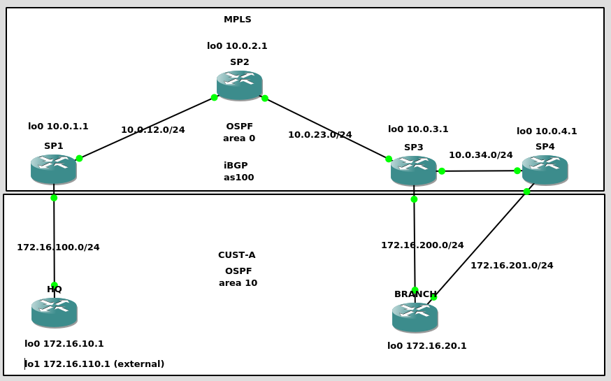
The big picture is: CE (HQ, BRANCH) routers are running OSPF with the PE (SP1/3/4) routers. The PE routers redistribute these OSPF routes into BGP and then converts them to VPNv4 NLRI. These VPNv4 NLRI are advetised to other PE routers via BGP. The PE also converts these VPNv4 routes back into OSPF and then off to the CE router.
Now in more detail, let’s see where we can have a routing loop:
1) HQ sends a LSA1 to SP1 with Lo:172.16.10.1/32 and the connected network to PE 172.16.100.0/24
HQ#show ip ospf database router internal self-originate

            OSPF Router with ID (172.16.110.1) (Process ID 1)

		Router Link States (Area 10)

  Now in min table
  Table index: 42 min 17 sec
  LS age: 321
  Options: (No TOS-capability, DC)
  LS Type: Router Links
  Link State ID: 172.16.110.1
  Advertising Router: 172.16.110.1
  LS Seq Number: 80000003
  Checksum: 0x7247
  Length: 48
  AS Boundary Router
  Number of Links: 2

    Link connected to: a Stub Network
     (Link ID) Network/subnet number: 172.16.10.1
     (Link Data) Network Mask: 255.255.255.255
      Number of TOS metrics: 0
       TOS 0 Metrics: 1

    Link connected to: a Transit Network
     (Link ID) Designated Router address: 172.16.100.1
     (Link Data) Router Interface address: 172.16.100.1
      Number of TOS metrics: 0
       TOS 0 Metrics: 1
2) SP1 received the new OSPF route from HQ (172.16.10.1/32) and it is redistributed into BGP so other PEs can receive it (SP3 and SP4) as a VPNv4. The connected 172.16.100.0/24 is as well redistributed into BGP
SP1#show ip ospf database router internal adv-router 172.16.110.1

            OSPF Router with ID (10.0.1.1) (Process ID 1)

            OSPF Router with ID (172.16.100.254) (Process ID 10)

		Router Link States (Area 10)

  Routing Bit Set on this LSA
  Now in min table
  Table index: 45 min 42 sec
  LS age: 648
  Options: (No TOS-capability, DC)
  LS Type: Router Links
  Link State ID: 172.16.110.1
  Advertising Router: 172.16.110.1
  LS Seq Number: 80000003
  Checksum: 0x7247
  Length: 48
  AS Boundary Router
  Number of Links: 2

    Link connected to: a Stub Network
     (Link ID) Network/subnet number: 172.16.10.1
     (Link Data) Network Mask: 255.255.255.255
      Number of TOS metrics: 0
       TOS 0 Metrics: 1

    Link connected to: a Transit Network
     (Link ID) Designated Router address: 172.16.100.1
     (Link Data) Router Interface address: 172.16.100.1
      Number of TOS metrics: 0
       TOS 0 Metrics: 1


SP1#
SP1#show ip route vrf CUST-A

Routing Table: CUST-A
Codes: C - connected, S - static, R - RIP, M - mobile, B - BGP
       D - EIGRP, EX - EIGRP external, O - OSPF, IA - OSPF inter area
       N1 - OSPF NSSA external type 1, N2 - OSPF NSSA external type 2
       E1 - OSPF external type 1, E2 - OSPF external type 2
       i - IS-IS, su - IS-IS summary, L1 - IS-IS level-1, L2 - IS-IS level-2
       ia - IS-IS inter area, * - candidate default, U - per-user static route
       o - ODR, P - periodic downloaded static route

Gateway of last resort is not set

     172.16.0.0/16 is variably subnetted, 6 subnets, 2 masks
B       172.16.200.0/24 [200/0] via 10.0.3.1, 00:41:47
B       172.16.201.0/24 [200/0] via 10.0.4.1, 00:41:47
B       172.16.20.1/32 [200/2] via 10.0.3.1, 00:41:47
O       172.16.10.1/32 [110/2] via 172.16.100.1, 00:43:58, FastEthernet0/0
O E1    172.16.110.1/32 [110/21] via 172.16.100.1, 00:43:58, FastEthernet0/0
C       172.16.100.0/24 is directly connected, FastEthernet0/0
SP1#
SP1#show ip bgp vpnv4 all
BGP table version is 14, local router ID is 10.0.1.1
Status codes: s suppressed, d damped, h history, * valid, > best, i - internal,
              r RIB-failure, S Stale
Origin codes: i - IGP, e - EGP, ? - incomplete

   Network          Next Hop            Metric LocPrf Weight Path
Route Distinguisher: 100:1 (default for vrf CUST-A)
*> 172.16.10.1/32   172.16.100.1             2         32768 ?
* i172.16.20.1/32   10.0.4.1                 2    100      0 ?
*>i                 10.0.3.1                 2    100      0 ?
*> 172.16.100.0/24  0.0.0.0                  0         32768 ?
*> 172.16.110.1/32  172.16.100.1            21         32768 ?
* i172.16.200.0/24  10.0.4.1                 2    100      0 ?
*>i                 10.0.3.1                 0    100      0 ?
*>i172.16.201.0/24  10.0.4.1                 0    100      0 ?
* i                 10.0.3.1                 2    100      0 ?
SP1#
It is important to notice how the VPNv4 for 172.16.10.1/32 is built in SP1. Based on the rfc section 4.2.6 “Handling LSAs from the CE” we see the following:
When a PE router receives, from a CE router, any LSA with the DN bit [OSPF-DN] set, the information from that LSA MUST NOT be used by the route calculation. If a Type 5 LSA is received from the CE, and if it has an OSPF route tag value equal to the VPN Route Tag (see Section 4.2.5.2), then the information from that LSA MUST NOT be used by the route calculation.

Otherwise, the PE must examine the corresponding VRF.For every address prefix that was installed in the VRF by one of its associated OSPF instances, the PE must create a VPN-IPv4 route in BGP. Each such route will have some of the following Extended Communities attributes:

– The OSPF Domain Identifier Extended Communities attribute. If the OSPF instance that installed the route has a non-NULL primary Domain Identifier, this MUST be present; if that OSPF instance has only a NULL Domain Identifier, it MAY be omitted. This attribute is encoded with a two-byte type field, and its type is 0005, 0105, or 0205. For backward compatibility, the type 8005 MAY be used as well and is treated as if it were 0005. If the OSPF instance has a NULL Domain Identifier, and the OSPF Domain Identifier Extended Communities attribute is present, then the attribute’s value field must be all zeroes, and its type field may be any of 0005, 0105, 0205, or 8005.

– OSPF Route Type Extended Communities Attribute. This attribute MUST be present. It is encoded with a two-byte type field, and its type is 0306. To ensure backward compatibility, the type 8000 SHOULD be accepted as well and treated as if it were type 0306. The remaining six bytes of the Attribute are encoded as follows:

     Area Number – Route Type – Options
So the very first paragraph is our answer when we reach SP3 (when dealing with a LSA3) and there is no loop. And the second paragrah is our answer when delaling with a LS5 and avoid a loop (more of this later). So this is our VPNv4 for 172.16.10.1/32
SP1#
SP1#show ip bgp vpnv4 rd 100:1 172.16.10.1/32
BGP routing table entry for 100:1:172.16.10.1/32, version 5
Paths: (1 available, best #1, table CUST-A)
  Advertised to update-groups:
        2
  Local
    172.16.100.1 from 0.0.0.0 (10.0.1.1)
      Origin incomplete, metric 2, localpref 100, weight 32768, valid, sourced, best
      Extended Community: RT:1:100 OSPF DOMAIN ID:0x0005:0x0000000A0200
        OSPF RT:0.0.0.10:2:0 OSPF ROUTER ID:172.16.100.254:0
      mpls labels in/out 21/nolabel
SP1#
So the extended communities generated from being a OSPF prefix are OSPF DOMAIN ID, OSPF Route Type (RT) and OSPF ROUTER ID.
I haven’t configured “ospf domain ID” in any router so Cisco IOS is generating one for itself (although it should be NULL) in OSPF DOMAIN ID.
For OSPF RT, we have are 10 (0.0.0.10) and LSA2 (although it should be LSA1). ROUTER ID is the expected one.
3) SP2 is just a P router so it is transparent here. Doesnt know anything about BGP, VPNv4, etc. It just does LDP and IGP.
SP2#show ip bgp summary
% BGP not active

SP2#show ip route ospf
     10.0.0.0/8 is variably subnetted, 7 subnets, 2 masks
O       10.0.3.1/32 [110/2] via 10.0.23.1, 00:45:04, GigabitEthernet2/0
O       10.0.1.1/32 [110/2] via 10.0.12.1, 00:44:54, GigabitEthernet1/0
O       10.0.4.1/32 [110/3] via 10.0.23.1, 00:44:54, GigabitEthernet2/0
O       10.0.34.0/24 [110/2] via 10.0.23.1, 00:44:54, GigabitEthernet2/0
SP2#
4) SP3 received the new VPNv4, it is redistributed from BGP to OSPF as a LSA3 (The MPLS backbone is a super OSPF area 0). If we pay attention to the details of the LSA3 (Summary) from HQ prefix 172.16.10.1/32 “show ip ospf database summary 172.16.10.1” we can see two details. First, the two LSA are one from SP3 (advert router 172.16.200.254) and the other from SP4 (advert router 172.16.201.254). Second, both show “Downward” in the options field. As stated earlier, this is directed by the rfc for any PE sending a LSA3. So, if iBGP has AD of 200 and OSPF has AD of 110. How come we have installed the BGP prefix in the routing table for 172.16.10.1/32 instead of the OSPF prefix coming from SP4. As per the standard mentioned earlier, if a PE router receives an OSPF prefix with the down bit enabled (“Downward”), the PE router ignores that prefix. The “Downward” bit is saying the prefix is coming from another PE in the same area so if you accept it, you will trigger a routing loop. Keep in mind that SP4 is doing the same thing as we see below in the commands for SP3. If SP3 accepts the OSPF prefix from SP4 for reaching 172.16.10.1/32 (HQ), SP4 is doing the same thing, accepting the SP3 prefix for reaching 172.16.10.1/32 (HQ). So SP3 would send traffic to SP4, and SP4 would return it back to SP3. When both SP3/SP4 learn the OSPF prefix from each other, they will stop redistributing the BGP prefix (that is coming from SP1/HQ) into OSPF so we reach a point where there is no more LSA3 for 172.16.10.1! and the process starts again. As well SP3/4 will redistribute the OPSF prefix learned from the other SP into BGP. So we are back to the intial stage, SP3/SP4 only have the BGP prefix for 172.16.10.1 (from SP2 or SP3/4), as it is the best route, it is redistributed to OSPF, and you know what happens next.
SP3#show ip bgp vpnv4 all
BGP table version is 13, local router ID is 10.0.3.1
Status codes: s suppressed, d damped, h history, * valid, > best, i - internal,
              r RIB-failure, S Stale
Origin codes: i - IGP, e - EGP, ? - incomplete

   Network          Next Hop            Metric LocPrf Weight Path
Route Distinguisher: 100:1 (default for vrf CUST-A)
*>i172.16.10.1/32   10.0.1.1                 2    100      0 ?
* i172.16.20.1/32   10.0.4.1                 2    100      0 ?
*>                  172.16.200.1             2         32768 ?
*>i172.16.100.0/24  10.0.1.1                 0    100      0 ?
*>i172.16.110.1/32  10.0.1.1                21    100      0 ?
* i172.16.200.0/24  10.0.4.1                 2    100      0 ?
*>                  0.0.0.0                  0         32768 ?
* i172.16.201.0/24  10.0.4.1                 0    100      0 ?
*>                  172.16.200.1             2         32768 ?
SP3#
SP3#
SP3#show ip route vrf CUST-A

Routing Table: CUST-A
Codes: C - connected, S - static, R - RIP, M - mobile, B - BGP
       D - EIGRP, EX - EIGRP external, O - OSPF, IA - OSPF inter area
       N1 - OSPF NSSA external type 1, N2 - OSPF NSSA external type 2
       E1 - OSPF external type 1, E2 - OSPF external type 2
       i - IS-IS, su - IS-IS summary, L1 - IS-IS level-1, L2 - IS-IS level-2
       ia - IS-IS inter area, * - candidate default, U - per-user static route
       o - ODR, P - periodic downloaded static route

Gateway of last resort is not set

     172.16.0.0/16 is variably subnetted, 6 subnets, 2 masks
C       172.16.200.0/24 is directly connected, FastEthernet0/0
O       172.16.201.0/24 [110/2] via 172.16.200.1, 00:45:46, FastEthernet0/0
O       172.16.20.1/32 [110/2] via 172.16.200.1, 00:45:46, FastEthernet0/0
B       172.16.10.1/32 [200/2] via 10.0.1.1, 00:43:35
B       172.16.110.1/32 [200/21] via 10.0.1.1, 00:43:35
B       172.16.100.0/24 [200/0] via 10.0.1.1, 00:43:35
SP3#
SP3#show ip ospf database

            OSPF Router with ID (10.0.3.1) (Process ID 1)

		Router Link States (Area 0)

Link ID         ADV Router      Age         Seq#       Checksum Link count
10.0.1.1        10.0.1.1        1076        0x80000003 0x00D9F2 2
10.0.2.1        10.0.2.1        1132        0x80000004 0x00D79A 3
10.0.3.1        10.0.3.1        1105        0x80000004 0x0083C1 3
10.0.4.1        10.0.4.1        1095        0x80000003 0x00D0C5 2

		Net Link States (Area 0)

Link ID         ADV Router      Age         Seq#       Checksum
10.0.12.2       10.0.2.1        1132        0x80000002 0x00FFFA
10.0.23.1       10.0.3.1        1105        0x80000002 0x009F4E
10.0.34.2       10.0.4.1        1095        0x80000002 0x002BB3

            OSPF Router with ID (172.16.200.254) (Process ID 10)

		Router Link States (Area 10)

Link ID         ADV Router      Age         Seq#       Checksum Link count
172.16.20.1     172.16.20.1     1105        0x80000004 0x00750C 3
172.16.200.254  172.16.200.254  1116        0x80000003 0x0059C2 1
172.16.201.254  172.16.201.254  1121        0x80000003 0x005DBA 1

		Net Link States (Area 10)

Link ID         ADV Router      Age         Seq#       Checksum
172.16.200.254  172.16.200.254  1116        0x80000002 0x00F4E4
172.16.201.254  172.16.201.254  1121        0x80000002 0x00EBEA

		Summary Net Link States (Area 10)

Link ID         ADV Router      Age         Seq#       Checksum
172.16.10.1     172.16.200.254  1116        0x80000002 0x000C61
172.16.10.1     172.16.201.254  1121        0x80000002 0x000567
172.16.100.0    172.16.200.254  1116        0x80000002 0x002AEA
172.16.100.0    172.16.201.254  1121        0x80000002 0x0023F0

		Type-5 AS External Link States

Link ID         ADV Router      Age         Seq#       Checksum Tag
172.16.110.1    172.16.200.254  1116        0x80000002 0x005FD9 3489661028
172.16.110.1    172.16.201.254  1121        0x80000002 0x0058DF 3489661028
SP3#
SP3#
SP3#
SP3#show ip ospf database  summary 172.16.10.1

            OSPF Router with ID (10.0.3.1) (Process ID 1)

            OSPF Router with ID (172.16.200.254) (Process ID 10)

		Summary Net Link States (Area 10)

  LS age: 1127
  Options: (No TOS-capability, DC, Downward)
  LS Type: Summary Links(Network)
  Link State ID: 172.16.10.1 (summary Network Number)
  Advertising Router: 172.16.200.254
  LS Seq Number: 80000002
  Checksum: 0xC61
  Length: 28
  Network Mask: /32
	TOS: 0 	Metric: 2

  LS age: 1132
  Options: (No TOS-capability, DC, Downward)
  LS Type: Summary Links(Network)
  Link State ID: 172.16.10.1 (summary Network Number)
  Advertising Router: 172.16.201.254
  LS Seq Number: 80000002
  Checksum: 0x567
  Length: 28
  Network Mask: /32
	TOS: 0 	Metric: 2

SP3#
Like we did in SP1, let’s see how SP3 deals with the VPNv4 for 172.16.10.1/32.
Based on th rfc “4.2.8” VPNv4 Routes received via BGP, we need to check “4.2.8.1 External Routes” (LSA5/7) and “4.2.8.2 Summary Routes” (LSA3) and the VPNv4 received:
SP3#show ip bgp vpnv4 rd 100:1 172.16.10.1/32
BGP routing table entry for 100:1:172.16.10.1/32, version 8
Paths: (1 available, best #1, table CUST-A)
  Not advertised to any peer
  Local
    10.0.1.1 (metric 3) from 10.0.1.1 (10.0.1.1)
      Origin incomplete, metric 2, localpref 100, valid, internal, best
      Extended Community: RT:1:100 OSPF DOMAIN ID:0x0005:0x0000000A0200
        OSPF RT:0.0.0.10:2:0 OSPF ROUTER ID:172.16.100.254:0
      mpls labels in/out nolabel/21
SP3#
The DOMAIN ID has to match as we haven’t defined it. OSPF RT, is telling that is coming from OSPF area 10 and non-external. So SP3 can generate a LSA3 for 172.16.10.1/32 as we have OSPF area 10 defined too.
5) From SP4 perspective. Same view as SP3. SP4 ignores LSA3 with Down-bit.
SP4#show ip bgp vpnv4 all
BGP table version is 13, local router ID is 10.0.4.1
Status codes: s suppressed, d damped, h history, * valid, > best, i - internal,
              r RIB-failure, S Stale
Origin codes: i - IGP, e - EGP, ? - incomplete

   Network          Next Hop            Metric LocPrf Weight Path
Route Distinguisher: 100:1 (default for vrf CUST-A)
*>i172.16.10.1/32   10.0.1.1                 2    100      0 ?
* i172.16.20.1/32   10.0.3.1                 2    100      0 ?
*>                  172.16.201.1             2         32768 ?
*>i172.16.100.0/24  10.0.1.1                 0    100      0 ?
*>i172.16.110.1/32  10.0.1.1                21    100      0 ?
* i172.16.200.0/24  10.0.3.1                 0    100      0 ?
*>                  172.16.201.1             2         32768 ?
* i172.16.201.0/24  10.0.3.1                 2    100      0 ?
*>                  0.0.0.0                  0         32768 ?
SP4#
SP4#
SP4#show ip ospf database summary 172.16.10.1

            OSPF Router with ID (10.0.4.1) (Process ID 1)

            OSPF Router with ID (172.16.201.254) (Process ID 10)

		Summary Net Link States (Area 10)

  LS age: 1489
  Options: (No TOS-capability, DC, Downward)
  LS Type: Summary Links(Network)
  Link State ID: 172.16.10.1 (summary Network Number)
  Advertising Router: 172.16.200.254
  LS Seq Number: 80000003
  Checksum: 0xA62
  Length: 28
  Network Mask: /32
	TOS: 0 	Metric: 2

  LS age: 1475
  Options: (No TOS-capability, DC, Downward)
  LS Type: Summary Links(Network)
  Link State ID: 172.16.10.1 (summary Network Number)
  Advertising Router: 172.16.201.254
  LS Seq Number: 80000003
  Checksum: 0x368
  Length: 28
  Network Mask: /32
	TOS: 0 	Metric: 2

SP4#
SP4#show ip route vrf CUST-A

Routing Table: CUST-A
Codes: C - connected, S - static, R - RIP, M - mobile, B - BGP
       D - EIGRP, EX - EIGRP external, O - OSPF, IA - OSPF inter area
       N1 - OSPF NSSA external type 1, N2 - OSPF NSSA external type 2
       E1 - OSPF external type 1, E2 - OSPF external type 2
       i - IS-IS, su - IS-IS summary, L1 - IS-IS level-1, L2 - IS-IS level-2
       ia - IS-IS inter area, * - candidate default, U - per-user static route
       o - ODR, P - periodic downloaded static route

Gateway of last resort is not set

     172.16.0.0/16 is variably subnetted, 6 subnets, 2 masks
O       172.16.200.0/24 [110/2] via 172.16.201.1, 01:31:12, FastEthernet3/0
C       172.16.201.0/24 is directly connected, FastEthernet3/0
O       172.16.20.1/32 [110/2] via 172.16.201.1, 01:31:12, FastEthernet3/0
B       172.16.10.1/32 [200/2] via 10.0.1.1, 01:28:57
B       172.16.110.1/32 [200/21] via 10.0.1.1, 01:28:57
B       172.16.100.0/24 [200/0] via 10.0.1.1, 01:28:57
SP4#
6) And Finally, BRANCH. It can see the prefix 172.16.10.1/32 (HQ) via two paths as we would expect. And without routing loops (the routes has been installed for over 1h 30minutes). BRANCH doesnt react to the Down-Bit so it accepts the LSA3 from SP2/3 and install the OSPF prefix.
BRANCH#show ip route
Codes: C - connected, S - static, R - RIP, M - mobile, B - BGP
       D - EIGRP, EX - EIGRP external, O - OSPF, IA - OSPF inter area
       N1 - OSPF NSSA external type 1, N2 - OSPF NSSA external type 2
       E1 - OSPF external type 1, E2 - OSPF external type 2
       i - IS-IS, su - IS-IS summary, L1 - IS-IS level-1, L2 - IS-IS level-2
       ia - IS-IS inter area, * - candidate default, U - per-user static route
       o - ODR, P - periodic downloaded static route

Gateway of last resort is not set

     172.16.0.0/16 is variably subnetted, 6 subnets, 2 masks
C       172.16.200.0/24 is directly connected, FastEthernet0/0
C       172.16.201.0/24 is directly connected, FastEthernet3/0
C       172.16.20.0/24 is directly connected, Loopback0
O IA    172.16.10.1/32 [110/3] via 172.16.201.254, 01:30:38, FastEthernet3/0
                       [110/3] via 172.16.200.254, 01:30:39, FastEthernet0/0
O E1    172.16.110.1/32 [110/22] via 172.16.201.254, 01:30:34, FastEthernet3/0
                        [110/22] via 172.16.200.254, 01:30:34, FastEthernet0/0
O IA    172.16.100.0/24 [110/2] via 172.16.201.254, 01:30:38, FastEthernet3/0
                        [110/2] via 172.16.200.254, 01:30:39, FastEthernet0/0
BRANCH#
BRANCH#
BRANCH#
BRANCH#show ip ospf database summary 172.16.10.1

            OSPF Router with ID (172.16.20.1) (Process ID 1)

		Summary Net Link States (Area 10)

  Routing Bit Set on this LSA
  LS age: 1599
  Options: (No TOS-capability, DC, Downward)
  LS Type: Summary Links(Network)
  Link State ID: 172.16.10.1 (summary Network Number)
  Advertising Router: 172.16.200.254
  LS Seq Number: 80000003
  Checksum: 0xA62
  Length: 28
  Network Mask: /32
	TOS: 0 	Metric: 2

  Routing Bit Set on this LSA
  LS age: 1587
  Options: (No TOS-capability, DC, Downward)
  LS Type: Summary Links(Network)
  Link State ID: 172.16.10.1 (summary Network Number)
  Advertising Router: 172.16.201.254
  LS Seq Number: 80000003
  Checksum: 0x368
  Length: 28
  Network Mask: /32
	TOS: 0 	Metric: 2

BRANCH#
So, we have seen the Down-bit in action for LSA3. But what about the external LSA: LSA5 and LSA7? How we avoid routing loops for them?
In this case, we have the “tag” field. This is explained in the rfc too.
1) In the same scenario, we have HQ router advertising 172.16.110.1/32 as LSA5 External.
HQ#
HQ#show ip interface brief
Interface                  IP-Address      OK? Method Status                Protocol
FastEthernet0/0            172.16.100.1    YES NVRAM  up                    up
GigabitEthernet1/0         unassigned      YES NVRAM  administratively down down
GigabitEthernet2/0         unassigned      YES NVRAM  administratively down down
FastEthernet3/0            unassigned      YES NVRAM  administratively down down
FastEthernet3/1            unassigned      YES NVRAM  administratively down down
Loopback0                  172.16.10.1     YES NVRAM  up                    up
Loopback1                  172.16.110.1    YES NVRAM  up                    up
HQ#
HQ#
HQ#
HQ#show ip ospf database

            OSPF Router with ID (172.16.110.1) (Process ID 1)

		Router Link States (Area 10)

Link ID         ADV Router      Age         Seq#       Checksum Link count
172.16.100.254  172.16.100.254  1270        0x80000005 0x00D7D1 1
172.16.110.1    172.16.110.1    1272        0x80000005 0x006E49 2

		Net Link States (Area 10)

Link ID         ADV Router      Age         Seq#       Checksum
172.16.100.1    172.16.110.1    1272        0x80000004 0x007824

		Summary Net Link States (Area 10)

Link ID         ADV Router      Age         Seq#       Checksum
172.16.20.1     172.16.100.254  1270        0x80000004 0x00586D
172.16.200.0    172.16.100.254  1270        0x80000004 0x00947E
172.16.201.0    172.16.100.254  1270        0x80000004 0x008988

		Type-5 AS External Link States

Link ID         ADV Router      Age         Seq#       Checksum Tag
172.16.110.1    172.16.110.1    1272        0x80000004 0x007253 0
HQ#
HQ#
HQ#show ip ospf database external

            OSPF Router with ID (172.16.110.1) (Process ID 1)

		Type-5 AS External Link States

  LS age: 1276
  Options: (No TOS-capability, DC)
  LS Type: AS External Link
  Link State ID: 172.16.110.1 (External Network Number )
  Advertising Router: 172.16.110.1
  LS Seq Number: 80000004
  Checksum: 0x7253
  Length: 36
  Network Mask: /32
	Metric Type: 1 (Comparable directly to link state metric)
	TOS: 0
	Metric: 20
	Forward Address: 0.0.0.0
	External Route Tag: 0

HQ#
2) SP1 sees 172.16.110.1/32 as OSPF E1. And redistribute it into BGP and creates a VPNv4
SP1#
SP1#show ip route vrf CUST-A

Routing Table: CUST-A
Codes: C - connected, S - static, R - RIP, M - mobile, B - BGP
       D - EIGRP, EX - EIGRP external, O - OSPF, IA - OSPF inter area
       N1 - OSPF NSSA external type 1, N2 - OSPF NSSA external type 2
       E1 - OSPF external type 1, E2 - OSPF external type 2
       i - IS-IS, su - IS-IS summary, L1 - IS-IS level-1, L2 - IS-IS level-2
       ia - IS-IS inter area, * - candidate default, U - per-user static route
       o - ODR, P - periodic downloaded static route

Gateway of last resort is not set

     172.16.0.0/16 is variably subnetted, 6 subnets, 2 masks
B       172.16.200.0/24 [200/0] via 10.0.3.1, 02:00:18
B       172.16.201.0/24 [200/0] via 10.0.4.1, 02:00:18
B       172.16.20.1/32 [200/2] via 10.0.3.1, 02:00:18
O       172.16.10.1/32 [110/2] via 172.16.100.1, 02:02:29, FastEthernet0/0
O E1    172.16.110.1/32 [110/21] via 172.16.100.1, 02:02:29, FastEthernet0/0
C       172.16.100.0/24 is directly connected, FastEthernet0/0
SP1#
SP1#
SP1#
SP1#show ip ospf database

            OSPF Router with ID (10.0.1.1) (Process ID 1)

		Router Link States (Area 0)

Link ID         ADV Router      Age         Seq#       Checksum Link count
10.0.1.1        10.0.1.1        1303        0x80000005 0x00D5F4 2
10.0.2.1        10.0.2.1        1350        0x80000006 0x00D39C 3
10.0.3.1        10.0.3.1        1554        0x80000006 0x007FC3 3
10.0.4.1        10.0.4.1        1352        0x80000005 0x00CCC7 2

		Net Link States (Area 0)

Link ID         ADV Router      Age         Seq#       Checksum
10.0.12.2       10.0.2.1        1350        0x80000004 0x00FBFC
10.0.23.1       10.0.3.1        1554        0x80000004 0x009B50
10.0.34.2       10.0.4.1        1352        0x80000004 0x0027B5

            OSPF Router with ID (172.16.100.254) (Process ID 10)

		Router Link States (Area 10)

Link ID         ADV Router      Age         Seq#       Checksum Link count
172.16.100.254  172.16.100.254  1400        0x80000005 0x00D7D1 1
172.16.110.1    172.16.110.1    1405        0x80000005 0x006E49 2

		Net Link States (Area 10)

Link ID         ADV Router      Age         Seq#       Checksum
172.16.100.1    172.16.110.1    1405        0x80000004 0x007824

		Summary Net Link States (Area 10)

Link ID         ADV Router      Age         Seq#       Checksum
172.16.20.1     172.16.100.254  1400        0x80000004 0x00586D
172.16.200.0    172.16.100.254  1400        0x80000004 0x00947E
172.16.201.0    172.16.100.254  1400        0x80000004 0x008988

		Type-5 AS External Link States

Link ID         ADV Router      Age         Seq#       Checksum Tag
172.16.110.1    172.16.110.1    1405        0x80000004 0x007253 0
SP1#
SP1#
SP1#
SP1#show ip ospf database external

            OSPF Router with ID (10.0.1.1) (Process ID 1)

            OSPF Router with ID (172.16.100.254) (Process ID 10)

		Type-5 AS External Link States

  Routing Bit Set on this LSA
  LS age: 1409
  Options: (No TOS-capability, DC)
  LS Type: AS External Link
  Link State ID: 172.16.110.1 (External Network Number )
  Advertising Router: 172.16.110.1
  LS Seq Number: 80000004
  Checksum: 0x7253
  Length: 36
  Network Mask: /32
	Metric Type: 1 (Comparable directly to link state metric)
	TOS: 0
	Metric: 20
	Forward Address: 0.0.0.0
	External Route Tag: 0

SP1#
SP1#show ip bgp vpnv4 all
BGP table version is 14, local router ID is 10.0.1.1
Status codes: s suppressed, d damped, h history, * valid, > best, i - internal,
              r RIB-failure, S Stale
Origin codes: i - IGP, e - EGP, ? - incomplete

   Network          Next Hop            Metric LocPrf Weight Path
Route Distinguisher: 100:1 (default for vrf CUST-A)
*> 172.16.10.1/32   172.16.100.1             2         32768 ?
* i172.16.20.1/32   10.0.4.1                 2    100      0 ?
*>i                 10.0.3.1                 2    100      0 ?
*> 172.16.100.0/24  0.0.0.0                  0         32768 ?
*> 172.16.110.1/32  172.16.100.1            21         32768 ?
* i172.16.200.0/24  10.0.4.1                 2    100      0 ?
*>i                 10.0.3.1                 0    100      0 ?
*>i172.16.201.0/24  10.0.4.1                 0    100      0 ?
* i                 10.0.3.1                 2    100      0 ?
SP1#
SP1#show ip bgp vpnv4 rd 100:1 172.16.110.1/32
BGP routing table entry for 100:1:172.16.110.1/32, version 7
Paths: (1 available, best #1, table CUST-A)
  Advertised to update-groups:
        2
  Local
    172.16.100.1 from 0.0.0.0 (10.0.1.1)
      Origin incomplete, metric 21, localpref 100, weight 32768, valid, sourced, best
      Extended Community: RT:1:100 OSPF DOMAIN ID:0x0005:0x0000000A0200
        OSPF RT:0.0.0.0:5:0 OSPF ROUTER ID:172.16.100.254:0
      mpls labels in/out 23/nolabel
SP1#
3) Again SP2, is transparent.
4) SP3 receives the VPNv4 for 172.16.110.1/32 from SP1. Installs it into BGP and then redistribute to OSPF. If we compare the ospf database output of SP1 with SP3. We see that SP3 has a different value for “tag” in 172.16.110.1/32. So that tags is created by SP3 when redistributing the BGP prefix to OSPF (based on the extended communities in the VPNv4 prefix). As per the rfc, the tag is generated based on the ASN (100). As are all our SPs are in the same ASN, the tag will be the same in all of PE generating the LSA from the VPNv4.
SP3#show ip bgp vpnv4  all
BGP table version is 13, local router ID is 10.0.3.1
Status codes: s suppressed, d damped, h history, * valid, > best, i - internal,
              r RIB-failure, S Stale
Origin codes: i - IGP, e - EGP, ? - incomplete

   Network          Next Hop            Metric LocPrf Weight Path
Route Distinguisher: 100:1 (default for vrf CUST-A)
*>i172.16.10.1/32   10.0.1.1                 2    100      0 ?
* i172.16.20.1/32   10.0.4.1                 2    100      0 ?
*>                  172.16.200.1             2         32768 ?
*>i172.16.100.0/24  10.0.1.1                 0    100      0 ?
*>i172.16.110.1/32  10.0.1.1                21    100      0 ?
* i172.16.200.0/24  10.0.4.1                 2    100      0 ?
*>                  0.0.0.0                  0         32768 ?
* i172.16.201.0/24  10.0.4.1                 0    100      0 ?
*>                  172.16.200.1             2         32768 ?
SP3#
SP3#
SP3#show ip route vrf CUST-A

Routing Table: CUST-A
Codes: C - connected, S - static, R - RIP, M - mobile, B - BGP
       D - EIGRP, EX - EIGRP external, O - OSPF, IA - OSPF inter area
       N1 - OSPF NSSA external type 1, N2 - OSPF NSSA external type 2
       E1 - OSPF external type 1, E2 - OSPF external type 2
       i - IS-IS, su - IS-IS summary, L1 - IS-IS level-1, L2 - IS-IS level-2
       ia - IS-IS inter area, * - candidate default, U - per-user static route
       o - ODR, P - periodic downloaded static route

Gateway of last resort is not set

     172.16.0.0/16 is variably subnetted, 6 subnets, 2 masks
C       172.16.200.0/24 is directly connected, FastEthernet0/0
O       172.16.201.0/24 [110/2] via 172.16.200.1, 02:06:43, FastEthernet0/0
O       172.16.20.1/32 [110/2] via 172.16.200.1, 02:06:43, FastEthernet0/0
B       172.16.10.1/32 [200/2] via 10.0.1.1, 02:04:33
B       172.16.110.1/32 [200/21] via 10.0.1.1, 02:04:33
B       172.16.100.0/24 [200/0] via 10.0.1.1, 02:04:33
SP3#
SP3#
SP3#show ip ospf database

            OSPF Router with ID (10.0.3.1) (Process ID 1)

		Router Link States (Area 0)

Link ID         ADV Router      Age         Seq#       Checksum Link count
10.0.1.1        10.0.1.1        1556        0x80000005 0x00D5F4 2
10.0.2.1        10.0.2.1        1602        0x80000006 0x00D39C 3
10.0.3.1        10.0.3.1        1804        0x80000006 0x007FC3 3
10.0.4.1        10.0.4.1        1602        0x80000005 0x00CCC7 2

		Net Link States (Area 0)

Link ID         ADV Router      Age         Seq#       Checksum
10.0.12.2       10.0.2.1        1602        0x80000004 0x00FBFC
10.0.23.1       10.0.3.1        1804        0x80000004 0x009B50
10.0.34.2       10.0.4.1        1602        0x80000004 0x0027B5

            OSPF Router with ID (172.16.200.254) (Process ID 10)

		Router Link States (Area 10)

Link ID         ADV Router      Age         Seq#       Checksum Link count
172.16.20.1     172.16.20.1     1640        0x80000006 0x00710E 3
172.16.200.254  172.16.200.254  1625        0x80000005 0x0055C4 1
172.16.201.254  172.16.201.254  1626        0x80000005 0x0059BC 1

		Net Link States (Area 10)

Link ID         ADV Router      Age         Seq#       Checksum
172.16.200.254  172.16.200.254  1625        0x80000004 0x00F0E6
172.16.201.254  172.16.201.254  1626        0x80000004 0x00E7EC

		Summary Net Link States (Area 10)

Link ID         ADV Router      Age         Seq#       Checksum
172.16.10.1     172.16.200.254  1625        0x80000004 0x000863
172.16.10.1     172.16.201.254  1626        0x80000004 0x000169
172.16.100.0    172.16.200.254  1625        0x80000004 0x0026EC
172.16.100.0    172.16.201.254  1626        0x80000004 0x001FF2

		Type-5 AS External Link States

Link ID         ADV Router      Age         Seq#       Checksum Tag
172.16.110.1    172.16.200.254  1625        0x80000004 0x005BDB 3489661028
172.16.110.1    172.16.201.254  1626        0x80000004 0x0054E1 3489661028
SP3#
5) So let’s see with details the VPNv4 prefix for 172.16.10.1/32 (OSPF LSA3) and 172.16.110.1/32 (OSPF LSA5). Both originated by HQ.
SP3#show ip bgp vpnv4 rd 100:1 172.16.10.1/32
BGP routing table entry for 100:1:172.16.10.1/32, version 8
Paths: (1 available, best #1, table CUST-A)
  Not advertised to any peer
  Local
    10.0.1.1 (metric 3) from 10.0.1.1 (10.0.1.1)
      Origin incomplete, metric 2, localpref 100, valid, internal, best
      Extended Community: RT:1:100 OSPF DOMAIN ID:0x0005:0x0000000A0200
        OSPF RT:0.0.0.10:2:0 OSPF ROUTER ID:172.16.100.254:0
      mpls labels in/out nolabel/21
SP3#
SP3#show ip bgp vpnv4 rd 100:1 172.16.110.1/32
BGP routing table entry for 100:1:172.16.110.1/32, version 11
Paths: (1 available, best #1, table CUST-A)
  Not advertised to any peer
  Local
    10.0.1.1 (metric 3) from 10.0.1.1 (10.0.1.1)
      Origin incomplete, metric 21, localpref 100, valid, internal, best
      Extended Community: RT:1:100 OSPF DOMAIN ID:0x0005:0x0000000A0200
        OSPF RT:0.0.0.0:5:0 OSPF ROUTER ID:172.16.100.254:0
      mpls labels in/out nolabel/23
SP3#
6) So SP3, based on the Extended communities, knows the VPNv4 prefix 172.16.110.1/32 was an OSPF LSA5 and it creates a tag. Keep in mind that SP4 is doing exactly the same thing as SP3:
SP4#
SP4#show ip route vrf CUST-A

Routing Table: CUST-A
Codes: C - connected, S - static, R - RIP, M - mobile, B - BGP
       D - EIGRP, EX - EIGRP external, O - OSPF, IA - OSPF inter area
       N1 - OSPF NSSA external type 1, N2 - OSPF NSSA external type 2
       E1 - OSPF external type 1, E2 - OSPF external type 2
       i - IS-IS, su - IS-IS summary, L1 - IS-IS level-1, L2 - IS-IS level-2
       ia - IS-IS inter area, * - candidate default, U - per-user static route
       o - ODR, P - periodic downloaded static route

Gateway of last resort is not set

     172.16.0.0/16 is variably subnetted, 6 subnets, 2 masks
O       172.16.200.0/24 [110/2] via 172.16.201.1, 02:18:34, FastEthernet3/0
C       172.16.201.0/24 is directly connected, FastEthernet3/0
O       172.16.20.1/32 [110/2] via 172.16.201.1, 02:18:34, FastEthernet3/0
B       172.16.10.1/32 [200/2] via 10.0.1.1, 02:16:19
B       172.16.110.1/32 [200/21] via 10.0.1.1, 02:16:19
B       172.16.100.0/24 [200/0] via 10.0.1.1, 02:16:19
SP4#
SP4#
SP4#
SP4#show ip ospf database

            OSPF Router with ID (10.0.4.1) (Process ID 1)

		Router Link States (Area 0)

Link ID         ADV Router      Age         Seq#       Checksum Link count
10.0.1.1        10.0.1.1        253         0x80000006 0x00D3F5 2
10.0.2.1        10.0.2.1        310         0x80000007 0x00D19D 3
10.0.3.1        10.0.3.1        504         0x80000007 0x007DC4 3
10.0.4.1        10.0.4.1        301         0x80000006 0x00CAC8 2

		Net Link States (Area 0)

Link ID         ADV Router      Age         Seq#       Checksum
10.0.12.2       10.0.2.1        310         0x80000005 0x00F9FD
10.0.23.1       10.0.3.1        504         0x80000005 0x009951
10.0.34.2       10.0.4.1        301         0x80000005 0x0025B6

            OSPF Router with ID (172.16.201.254) (Process ID 10)

		Router Link States (Area 10)

Link ID         ADV Router      Age         Seq#       Checksum Link count
172.16.20.1     172.16.20.1     315         0x80000007 0x006F0F 3
172.16.200.254  172.16.200.254  347         0x80000006 0x0053C5 1
172.16.201.254  172.16.201.254  315         0x80000006 0x0057BD 1

		Net Link States (Area 10)

Link ID         ADV Router      Age         Seq#       Checksum
172.16.200.254  172.16.200.254  347         0x80000005 0x00EEE7
172.16.201.254  172.16.201.254  315         0x80000005 0x00E5ED

		Summary Net Link States (Area 10)

Link ID         ADV Router      Age         Seq#       Checksum
172.16.10.1     172.16.200.254  347         0x80000005 0x000664
172.16.10.1     172.16.201.254  315         0x80000005 0x00FE6A
172.16.100.0    172.16.200.254  347         0x80000005 0x0024ED
172.16.100.0    172.16.201.254  315         0x80000005 0x001DF3

		Type-5 AS External Link States

Link ID         ADV Router      Age         Seq#       Checksum Tag
172.16.110.1    172.16.200.254  347         0x80000005 0x0059DC 3489661028
172.16.110.1    172.16.201.254  315         0x80000005 0x0052E2 3489661028
SP4#
SP4#
SP4#
SP4#show ip ospf database external 172.16.110.1

            OSPF Router with ID (10.0.4.1) (Process ID 1)

            OSPF Router with ID (172.16.201.254) (Process ID 10)

		Type-5 AS External Link States

  LS age: 350
  Options: (No TOS-capability, DC)
  LS Type: AS External Link
  Link State ID: 172.16.110.1 (External Network Number )
  Advertising Router: 172.16.200.254
  LS Seq Number: 80000005
  Checksum: 0x59DC
  Length: 36
  Network Mask: /32
	Metric Type: 1 (Comparable directly to link state metric)
	TOS: 0
	Metric: 21
	Forward Address: 0.0.0.0
	External Route Tag: 3489661028

  LS age: 319
  Options: (No TOS-capability, DC)
  LS Type: AS External Link
  Link State ID: 172.16.110.1 (External Network Number )
  Advertising Router: 172.16.201.254
  LS Seq Number: 80000005
  Checksum: 0x52E2
  Length: 36
  Network Mask: /32
	Metric Type: 1 (Comparable directly to link state metric)
	TOS: 0
	Metric: 21
	Forward Address: 0.0.0.0
	External Route Tag: 3489661028

SP4#
SP4#
SP4#
SP4#show ip bgp vpnv4 rd 100:1 172.16.10.1/32
BGP routing table entry for 100:1:172.16.10.1/32, version 8
Paths: (1 available, best #1, table CUST-A)
  Not advertised to any peer
  Local
    10.0.1.1 (metric 4) from 10.0.1.1 (10.0.1.1)
      Origin incomplete, metric 2, localpref 100, valid, internal, best
      Extended Community: RT:1:100 OSPF DOMAIN ID:0x0005:0x0000000A0200
        OSPF RT:0.0.0.10:2:0 OSPF ROUTER ID:172.16.100.254:0
      mpls labels in/out nolabel/21
SP4#
SP4#
SP4#show ip bgp vpnv4 rd 100:1 172.16.110.1/32
BGP routing table entry for 100:1:172.16.110.1/32, version 11
Paths: (1 available, best #1, table CUST-A)
  Not advertised to any peer
  Local
    10.0.1.1 (metric 4) from 10.0.1.1 (10.0.1.1)
      Origin incomplete, metric 21, localpref 100, valid, internal, best
      Extended Community: RT:1:100 OSPF DOMAIN ID:0x0005:0x0000000A0200
        OSPF RT:0.0.0.0:5:0 OSPF ROUTER ID:172.16.100.254:0
      mpls labels in/out nolabel/23
SP4#
7) As you can see, SP3 and SP4 are generating the same “tag” 3489661028 for the LSA5 172.16.110.1/32 (because they are in the same ASN 100). So as the receiving LSA for the other SP in the same Area 10 has the same tag, SP3/SP4 ignore the LSA. And again, the BGP prefix is installed in the routing table instead of the OSPF AD110 172.16.110.1/32 and we dont have a routing loop.
Design: When you aim for HA, even a single patch panel is a SPOF no matther how much redundancy you have in your transit providers, routers, switches, firewalls, etc etc. So, look for SPOF!
Documentation: For DC stuff, in my current employer we use patchmanager. It is supper handy for remote locations and it is our source of truth. Keep in mind that tool is as good as you keep it updated…. For example, for the PoPs we visit more often and we make more changes, we find more failures that we would like… For remote PoPs, as we know we are not going to come back for a couple of years, we are much more throrough. For network kit, we have RANCID+Git so we know always the lattest config and when changes where introduced (in 30m intervals at least).
Process: We follow a risk assesment for any change we plan to introduce. Then on Thursday we have a CAB metting to schedule what changes are going to happen during the weekend. The aim is to have several people from different teams to understand and have a say in what is going to happen. This has proobed very useful. Four pairs of eyes are better than half 🙂 Still you need to be regirous in this process
Even having all this into account, you will have an outage. Have a retrospective, learn from it (no finger pointing) and apply it. Trully agile 😛
When I was studying CCNP back in 2009, I found a lab for MPLS that was fantastic. It showed how to buid a MPLS L3VPN network from scratch. I managed to build that in my laptop with GNS3 at that time.
Now I want to review some MPLS features so I decided to install GNS3 and build that lab again. You can find it in my github account (that was gathering dust…):
I searched several pages to find out how to do it now a days. It seems it is mainly managed by python. This is what I had to do for Debian 10 (Testing)
Once I managed to run the program, I found some other issues.
First, you need to get the software to simulate the routers. I searched for recommended images for running MPLS and it seems c7200-adventerprisek9-mz.124-24.T2 was a good one. If you search for that, it will not be difficult to find somewhere to download it.
It took me a while but at the end I could create a lab with several routers, power them up and login to them.
As well, I modified GNS3 to use “terminator” as default terminal when connecting to the devices. That was handy.
There are many things you can configure with GNS3. Like a basic linux host to test (Alpine). I installed it as I think it will be usefull in the future:
There are many more things you can configure but for what I want, this is enough.
MPLS L3VPN
So once we have aworking GNS3 environment, we can get our hands dirty and create our MPLS L3VPN lab.
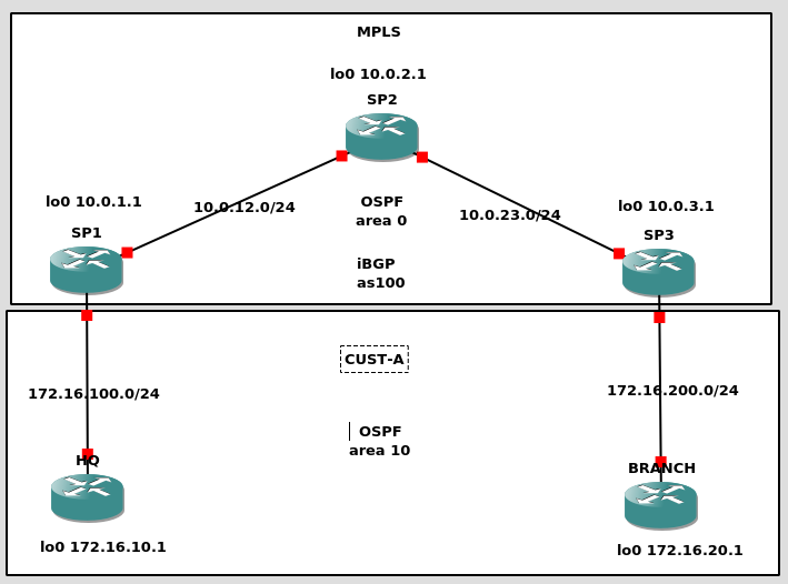
This is the diagram:
We are going to simulate a Service Provider (SP) network that is formed by SP1, SP2 and SP3. The customer network CUST-A is formed by HQ and Branch:
SP1 and SP3 will be PE routers (they will manage the L3VPN) (PE = Provider Edge)
SP2 will be just a P router (doesnt have visibility of any L3VPN, just handle labels) (P = Provider)
HQ and BRANCH are CPE routers (Customer Provider Edge). They interact with PE.
The SP network uses OSPF (area0 – backbone area) as IGP to build the iBGP full mesh (as100)
CUST-A is connected to our SP network in different locations. Internally is running its own routing and both locations are in the same OSPF area 10. So the prefixes learned in HQ and Branch should be seen as Inter-Area (IA). This is quite important.
So, lets get step by step:
1- IP addressing
We need to configure the IP connectivity in all links
SP1
---
!
interface Loopback0
 ip address 10.0.1.1 255.255.255.255
!
interface GigabitEthernet1/0
 description to SP2-P
 ip address 10.0.12.1 255.255.255.0
!
interface FastEthernet0/0
 description to HQ
 ip address 172.16.100.254 255.255.255.0
!


SP2
---
!
interface Loopback0
 ip address 10.0.2.1 255.255.255.255
!
interface GigabitEthernet1/0
 description to SP1-PE
 ip address 10.0.12.2 255.255.255.0
!
interface GigabitEthernet2/0
 description to SP3-PE
 ip address 10.0.23.2 255.255.255.0
!

SP3
---
!
interface Loopback0
 ip address 10.0.3.1 255.255.255.255
!
interface GigabitEthernet1/0
 description to SP2-P
 ip address 10.0.23.1 255.255.255.0
!
interface FastEthernet0/0
 description to BRANCH
 ip address 172.16.200.254 255.255.255.0
!

HQ
---
!
interface Loopback0
 ip address 172.16.10.1 255.255.255.0
!
interface FastEthernet0/0
 description to SP1-PE
 ip address 172.16.100.1 255.255.255.0
!

BRANCH
---
!
interface Loopback0
 ip address 172.16.20.1 255.255.255.0
!
interface FastEthernet0/0
 description to SP3-PE
 ip address 172.16.200.1 255.255.255.0
!
Verify you can ping each directly connected router:
HQ#ping 172.16.100.254

Type escape sequence to abort.
Sending 5, 100-byte ICMP Echos to 172.16.100.254, timeout is 2 seconds:
!!!!!
Success rate is 100 percent (5/5), round-trip min/avg/max = 12/16/20 ms
HQ#
2- Routing in SP
We are going to configure OSPF (area 0 – backbone) as IGP in our SP network. We only want the SP loopbacks and backbone links in OSPF.
SP1
---
router ospf 1
 network 10.0.1.0 0.0.0.255 area 0
 network 10.0.12.0 0.0.0.255 area 0

SP2
---
router ospf 1
 network 10.0.2.0 0.0.0.255 area 0
 network 10.0.12.0 0.0.0.255 area 0
 network 10.0.23.0 0.0.0.255 area 0

SP3
---
router ospf 1
 network 10.0.3.0 0.0.0.255 area 0
 network 10.0.23.0 0.0.0.255 area 0
Verify that OSFP comes up in all expected links. If SP2 has two neighbors, all good:
SP2#show ip ospf neighbor

Neighbor ID     Pri   State           Dead Time   Address         Interface
10.0.3.1          1   FULL/DR         00:00:36    10.0.23.1       GigabitEthernet2/0
10.0.1.1          1   FULL/DR         00:00:34    10.0.12.1       GigabitEthernet1/0
SP2#
3- MPLS in SP
Now we are going to configure MPLS in SP. We are going to use LDP for label distribution. The configuration is pretty easy, just enable LDP using Lo0 as router ID and configure mpls only in backbone links.
SP1
---
mpls ldp router-id Loopback0 force
!
interface GigabitEthernet1/0
 description to SP2-P
 mpls ip
!

SP2
---
mpls ldp router-id Loopback0 force
!
interface GigabitEthernet1/0
 description to SP1-PE
 mpls ip
!
interface GigabitEthernet2/0
 description to SP3-PE
 mpls ip
!

SP3
---
mpls ldp router-id Loopback0 force
!
interface GigabitEthernet1/0
 description to SP2-P
 mpls ip
!
Check that LDP neighbors come up. If SP2 has two, all good.
For SP, you need each customer in a VRF so you can isolate them and the customer can use any IP addressing schema. You need to make those IP prefixes unique inside SP if you want to exchange them via a routing protocol. For doing that, you need to create VPNV4 addresses that are a combination of the customer IP prefix and a RD (Router Distinguisher – 8 bytes). Each VRF has a RD and is locally significant, you could configure each PE with CUST-A using a different RD, but as best practive we keep the same RD per VRF. Having each VRF with a different RD, eachc customer cand use the same private IP prefix but to the SP eyes, after building the VPNV4, the customer prefixes will be diffierent and there will no be leaking (if you dont configure it). For exporting/importing prefixes in a VRF, we use RT (Route Target). And that is defined during the VRF creating too. Keep in mind that we only define VRFs in PE routers (SP1 and SP3). The P routers (SP2) dont need to know. In our case we are going to use RD 100:1 and RT 1:100.
The config above says that for each VPNv4 prefix we export from CUST-A VRF we add RT 1:100. And for any VPNv4 prefix with RT:1:00 learned by the router (more about this later in point 6) we will import it in CUST-A VRF.
Now we can configure the links to customers in their own VRF:
SP1
---
!
interface FastEthernet0/0
 description to HQ
 ip vrf forwarding CUST-A
 ip address 172.16.100.254 255.255.255.0
!

SP3
---
!
interface FastEthernet0/0
 description to BRANCH
 ip vrf forwarding CUST-A
 ip address 172.16.200.254 255.255.255.0
!
Now, let’s check if we keep the IP connectivity with CUST-A from our PE routers.
SP1#ping vrf CUST-A 172.16.100.1

Type escape sequence to abort.
Sending 5, 100-byte ICMP Echos to 172.16.100.1, timeout is 2 seconds:
!!!!!
Success rate is 100 percent (5/5), round-trip min/avg/max = 16/21/32 ms
SP1#
Keep in mind, that for CUST-A, all this is transparent.
5- Customer Routing
So now, we want our customer devices to exchange routes because they want reach each other (if not, why do you want a network 🙂 We are going to use OSPF in area 10 as routing protocol between CUST-A and SP. But SP is already using OSFP??? Yes, but keep in mind that we are using VRFs, and the OSPF implementation will be in the customer VRF. It will not interact with the SP OSPF Area 0. So we need to configure OSPF in the interfaces connecting to SP and interfaces we want to advertise (Lo0). And again, our SP2 (P) doesnt need to know anything about this.
HQ
!
router ospf 1
 log-adjacency-changes
 network 172.16.10.0 0.0.0.255 area 10
 network 172.16.100.0 0.0.0.255 area 10
!

BRANCH
!
router ospf 1
 log-adjacency-changes
 network 172.16.20.0 0.0.0.255 area 10
 network 172.16.200.0 0.0.0.255 area 10

SP1
!
router ospf 10 vrf CUST-A
 network 172.16.100.0 0.0.0.255 area 10
!

SP3
!
router ospf 10 vrf CUST-A
 network 172.16.200.0 0.0.0.255 area 10
!
Check that OSPF between CUST-A devices and SP comes up, and you are learning the CUST-A prefixes:
SP1#show ip ospf neighbor

Neighbor ID     Pri   State           Dead Time   Address         Interface
10.0.2.1          1   FULL/BDR        00:00:36    10.0.12.2       GigabitEthernet1/0
172.16.10.1       1   FULL/BDR        00:00:38    172.16.100.1    FastEthernet0/0
SP1#
SP1#show ip route vrf CUST-A

Routing Table: CUST-A
Codes: C - connected, S - static, R - RIP, M - mobile, B - BGP
       D - EIGRP, EX - EIGRP external, O - OSPF, IA - OSPF inter area
       N1 - OSPF NSSA external type 1, N2 - OSPF NSSA external type 2
       E1 - OSPF external type 1, E2 - OSPF external type 2
       i - IS-IS, su - IS-IS summary, L1 - IS-IS level-1, L2 - IS-IS level-2
       ia - IS-IS inter area, * - candidate default, U - per-user static route
       o - ODR, P - periodic downloaded static route

Gateway of last resort is not set

     172.16.0.0/16 is variably subnetted, 3 subnets, 2 masks
O       172.16.10.1/32 [110/2] via 172.16.100.1, 00:38:48, FastEthernet0/0
C       172.16.100.0/24 is directly connected, FastEthernet0/0
SP1#
In the output above, you will see that SP1 has two OSPF neighbors, one to SP2 (OSPF area 0 – backbone) and one to HQ (CUST-A VRF). As well, you will see that SP1 is learning Lo0 prefix from HQ via OSPF.
6- BGP
Now we have routing between SP1-HQ and SP3-BRANCH. But we dont have communication between HQ-BRANCH yet. And this is the goal at the end of the day.
So now, we need our PE routers to exchange the customer prefixes. We are going to use BGP/MP-BGP.
As we are in the same AS100 (Autonomous System) we are going to use iBGP (internal BGP). Following best practices, we are going to build our full mesh iBGP on loopbacks. iBGP relays on a IGP, and that is already configured via OSPF in our network.
SP1#show ip bgp summary
BGP router identifier 10.0.1.1, local AS number 100
BGP table version is 1, main routing table version 1

Neighbor        V          AS MsgRcvd MsgSent   TblVer  InQ OutQ Up/Down  State/PfxRcd
10.0.3.1        4        100      53      53        1    0    0 00:50:08        0
SP1#
So we have BGP between our PE routers. Now we need to configure the exchange of those VPNv4 routes so CUST-A devices can learn prefixes from its own network.
The above part is the MP-BGP part (MultiProtocol-BGP). Inside our BGP connection between SP1-SP3 we have enabled a type of exchange of prefixes for vpnv4.
But, we dont have VPNv4 prefixes yet.
SP1#show ip bgp vpnv4 all
BGP table version is 7, local router ID is 10.0.1.1
Status codes: s suppressed, d damped, h history, * valid, > best, i - internal,
              r RIB-failure, S Stale
Origin codes: i - IGP, e - EGP, ? - incomplete

   Network          Next Hop            Metric LocPrf Weight Path
SP1#
Because they need to be in the BGP table first. We have routing between PE-CE (ospf area 10) but we dont have any kind of redistribution between OSPF-BGP. Let’s do that:
SP1#show ip bgp vpnv4 all
BGP table version is 9, local router ID is 10.0.1.1
Status codes: s suppressed, d damped, h history, * valid, > best, i - internal,
              r RIB-failure, S Stale
Origin codes: i - IGP, e - EGP, ? - incomplete

   Network          Next Hop            Metric LocPrf Weight Path
Route Distinguisher: 100:1 (default for vrf CUST-A)
*> 172.16.10.1/32   172.16.100.1             2         32768 ?
*>i172.16.20.1/32   10.0.3.1                 2    100      0 ?
*> 172.16.100.0/24  0.0.0.0                  0         32768 ?
*>i172.16.200.0/24  10.0.3.1                 0    100      0 ?
SP1#
So now, we can see in SP1 the prefixes from HQ and BRANCH routers!
Now, let’s check the CUST-A routing table from SP1 and HQ:
SP1#show ip route vrf CUST-A

Routing Table: CUST-A
Codes: C - connected, S - static, R - RIP, M - mobile, B - BGP
       D - EIGRP, EX - EIGRP external, O - OSPF, IA - OSPF inter area
       N1 - OSPF NSSA external type 1, N2 - OSPF NSSA external type 2
       E1 - OSPF external type 1, E2 - OSPF external type 2
       i - IS-IS, su - IS-IS summary, L1 - IS-IS level-1, L2 - IS-IS level-2
       ia - IS-IS inter area, * - candidate default, U - per-user static route
       o - ODR, P - periodic downloaded static route

Gateway of last resort is not set

     172.16.0.0/16 is variably subnetted, 4 subnets, 2 masks
B       172.16.200.0/24 [200/0] via 10.0.3.1, 01:08:19
B       172.16.20.1/32 [200/2] via 10.0.3.1, 00:01:33
O       172.16.10.1/32 [110/2] via 172.16.100.1, 01:15:49, FastEthernet0/0
C       172.16.100.0/24 is directly connected, FastEthernet0/0
SP1#


HQ#show ip route
Codes: C - connected, S - static, R - RIP, M - mobile, B - BGP
       D - EIGRP, EX - EIGRP external, O - OSPF, IA - OSPF inter area
       N1 - OSPF NSSA external type 1, N2 - OSPF NSSA external type 2
       E1 - OSPF external type 1, E2 - OSPF external type 2
       i - IS-IS, su - IS-IS summary, L1 - IS-IS level-1, L2 - IS-IS level-2
       ia - IS-IS inter area, * - candidate default, U - per-user static route
       o - ODR, P - periodic downloaded static route

Gateway of last resort is not set

     172.16.0.0/16 is variably subnetted, 4 subnets, 2 masks
O IA    172.16.200.0/24 [110/2] via 172.16.100.254, 01:07:09, FastEthernet0/0
O IA    172.16.20.1/32 [110/3] via 172.16.100.254, 00:00:22, FastEthernet0/0
C       172.16.10.0/24 is directly connected, Loopback0
C       172.16.100.0/24 is directly connected, FastEthernet0/0
HQ#
HQ#
So from SP1, we can see that is learning BRANCH 172.16.200.0/24 and 172.16.20.1/32 via iBGP (from SP3 loopback 10.0.3.1). The 172.16.10.1/32 (HQ loopback) via OSPF.
From HQ, we see it is learning BRANCH Prefixes too and they come up as O IA. This is very important, and it is material for another post about OSPF Down-Bit.
7- Conclusion
We have IP connectivity between our CUST-A devices across a MPLS L3VPN
HQ#ping 172.16.20.1

Type escape sequence to abort.
Sending 5, 100-byte ICMP Echos to 172.16.20.1, timeout is 2 seconds:
!!!!!
Success rate is 100 percent (5/5), round-trip min/avg/max = 44/76/156 ms
HQ#
HQ#traceroute 172.16.20.1

Type escape sequence to abort.
Tracing the route to 172.16.20.1

  1 172.16.100.254 16 msec 8 msec 12 msec
  2 10.0.12.2 [MPLS: Labels 17/20 Exp 0] 72 msec 40 msec 60 msec
  3 172.16.200.254 [MPLS: Label 20 Exp 0] 52 msec 8 msec 60 msec
  4 172.16.200.1 40 msec 52 msec 40 msec
HQ#
We have built a MPLS L3VPN from the bottom up. There are many points that can be explained with much more detail but that wasnt the goal. Just wanted to build this MPLS network so I can do some hands-on troubleshooting and review a couple of concepts.
Ideally, at some point, I would like to build a MPLS Segment Routing GNS3 networks.
I was quite surprised about the backgroup and links between both sides. We know that there are still some big companies today that had collaborations with the regime in that time. But I didnt know any one related to today’s IT.
S3 is the Amazon service to store files in the cloud. It is reliable, very reliable, the expected time to lost a single file from a group of 10 million of them is 10000 years. Even other services on Amazon uses internally S3 to store its files. On the bad side, as it is one of the first services that Amazon created, it can be a headache to fine grain permissions form all its capabilites and evolutions, making it difficult to be sure that a file is not accesible for those that should not be allowed.
In S3 you can define what they call a bucket, which is like a directory in a filesystem. The name of the bucket must be unique, not only in your account but in the global namespace from all AWS accounts in the world. That means you have to be creative when picking a bucket name.
A bucket can be private or publicly accessible. In the public side, one of the special uses is to serve static content from as a web server, even html pages from your custom domain. But what if you want to allow users to download files, for example an image, and you don’t want the user to be able to make it public sharing the link to the image?
I’ve played today with a very useful feature for that case. It allows to have a private bucket that can temporary allow the access to a single file to GET or even PUT/POST for a limited amount of time. You’ll need to use AWS SDK of your favourite supported programming language or AWS CLI from command line, to query AWS API for a temporary authorized url. Let’s see how with an example from scratch, installing and using AWS CLI in a Debian based environment.
Make sure you have access to an AWS account (you already have one if you have an amazon.com account) and generate a pair of AWS Access Key and AWS Secret Access Key from web console.
$> sudo apt instal awscli
$> aws configure
AWS Access Key ID [None]:
AWS Secret Access Key [None]:
Default region name [None]: eu-west-1
Default output format [None]:
Create a local file called piticli with the content you prefer. Let’s create also a new S3 bucket using aws cli
# Create a convenience environment variable with a kind of random bucket name
$> BN="s3://thomarite-blog-test-$RANDOM"
# Let's actually create the bucket
$> aws s3 mb $BN
make_bucket: thomarite-blog-test-1337
# Let's see it exists
$> aws s3 ls
2020-04-16 23:01:27 thomarite-blog-test-1337
# Now let's upload piticli into the new bucket
$> aws s3 cp piticli $BN
2020-04-17 23:01:45          26 piticli
Now let’s create a presigned url for piticli and store it in PRESIGNED_URL env var. As you can see, the temporary URL includes the bucket name, the file name and new AWS Access Key and signature, and a hint about the expiration date.
# Store the URL into a env var for future use
$> PRESIGNED_URL=$(aws s3 presign $BN/piticli)
$> echo $PRESIGNED_URL
https://s3.eu-west-1.amazonaws.com/thomarite-blog-test-1337/piticli?AWSAccessKeyId=AKIAYSFFLHZCQSEPMZEF&Signature=x%2BWzELvYpzdVipOd67ez0z3Esws%3D&Expires=1587077637
That’s the public url and will be valid for 1h by default. You can set the expiration time in aws s3 presign command using the parameter --expires-in and set the seconds allowed until it expires.
Now you have a public url accessible by any browser. Let’s open it via curl:
$> curl -Ls $PRESIGNED_URL
piticli is now… sleeping
And finally to clean things up let’s remove all the files and the bucket in AWS
Today I had to troubleshoot a websocket issue. I had never dealt with this before. I was told that HAproxy config was fine that it was to be our NGFW doing something nasty at L7.
The connection directly to the server doing websocket was fine from my PC but for some requirement we need to put that server behing a HAproxy. From my PC to the haproxy that is doing “proxy” fore the websocket service failed…
Funny enough HAproxy and the websocket service were running in the same host.
As usual I took a look at the firewall logs. Nothing wrong there at first sight. I took a tcpdump from my pc when connecting to the websocket service and to the haproxy.
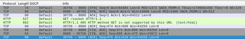
The service is very verbose and it is difficult to follow in the capture files as it spawns several connections. I went to the easy part, the capture to the haproxy was showing a lot of TCP retransmissions… The other trace to the websocket service was pretty clean.
Taking into account that the path from my PC to the haproxy server is the always the same (and I was going through a VPN) I could think it was a NGFW issue or something between HAproxy and the websocket service (that is a localhost connection).
As well, I was seeing weird things latency wise. Some TCP resets were taking more than 200ms to arrive to the server when the average RTT was 3ms.
I tried to take a tcpdump between the haproxy service and the websocket service just in case that packet loss was caused locally. The capture was chaos to follow. I had to understand better the sessions in HAproxy.
I changed direction and I went to the NGFW and created a rule that disabled any fancy security check for me to the haproxy server. I wanted to be sure the firewall was innocent.
It was. Same issue. I tried different browsers and always the same.
So I was nearly sure the problem was in HAproxy but I had to prove it. I kind of failed checking the backend connection (haproxy to websockt proxy) so I took again a look to the trace from my pc to haproxy. I was quite frustrated because there was so many connetions openned and then retransmissions started happening that I couldnt really see any problem.
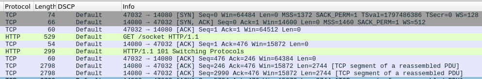
By luck, I noticed that in the good trace (the one going directly to the websocket service) I could see a HTTP GET request for “socket” from my PC. Keep in mind that I have no idea how websocket works. I tried to find a similar request in the haproxy trace, and I saw the problem….
Rejected HTTP GET socket request
and this is a good connection:
Successful HTTP GET socket request
So at the end, HAproxy was at fault (we dont know how to fix it though yet) and my firewall (for once) it is innocent.
The summary, I got overwhelmed by the TCP retransmissions. I was lucky that I saw the GET socket and I assumed that had to be the way to get the websocket connection established. So I should have started investigating how a websocket connections is stablished. As well, I didnt manage to find the HAproxy logs, I am pretty sure I should have found the same answer. So I need to learn to check that.
I learned something new. As usual, it didnt come easy neither quick 🙂
But at the end, it is not all about the Bloom filters. It is understanding how things work under the hood and see if they are actually delivering, if not, you should change your approach. So the debugging section “A secret weapon – a profiler” is very good. Profiling is not one of my strengths so the tools used are the ones I need to understand and use more often:
strace -cf
perf stat -d
perf record
perf record | head -n 20
perf annotate process_line --source
google-perftools' with kcachegrind
As well the reference to the performance numbers that are good to have in mind:
Notice the magnitude differences in the performance of different options.
Datacenters are far away so it takes a long time to send anything between them.
Memory is fast and disks are slow.
By using a cheap compression algorithm a lot (by a factor of 2) of network bandwidth can be saved.
Writes are 40 times more expensive than reads.
Global shared data is expensive. This is a fundamental limitation of distributed systems. The lock contention in shared heavily written objects kills performance as transactions become serialized and slow.
Architect for scaling writes.
Optimize for low write contention.
Optimize wide. Make writes as parallel as you can.
As well, “The lessons learned” is a great summary of his trip.
Sequential memory access great / Random memory access costly -> cache prefetching
Advanced data structures to fit L3: optimize for reduced number loads than the amount of memory used.