This week at work I have to deal with a couple of physical connections that were new for me. I am more familiar with LC connector and MTP is still something I am dealing with. So I learned about BiDir optics (LC) something never heard about it and the difference with SR4 optics (MTP). The vantage of using BiDir is that you can keep your current fiber install in place and upgrade from 10G to 40G without extra cost. But with SR4 you need to deploy MTP/MTO cabling although you can do breakouts (40G to4x10G or 100G to 4x25G). This is the blog entry I found quite useful for comparing both types. And this one just for BiDir.
As well, somewhere I read (can’t find the link), SR4 are more common than BiDir because is BiDir is proprietary so it has compatibility issues
I am not as up to speed with storage as I would like to but this blog gives you a quick intro for the different types of SSD.
As well, this week struggled a bit with a 100G port that had to connect as 4x25G to some servers. It was a bit of time since I dealt with something similar. Initially I though I had to wait for the servers to power up so once the link in the other side comes up and the switch recognizes the port as 25G and creates the necessary interfaces. But I had eth1/1 only. I was expecting eth1/1, eth1/2, eth1/3 and eth1/4… The three extra interfaces were created ONLY after I “forced” the speed setting to “25G” in eth1/1….. I hope I remember this for next time.
Some months ago I read about containerlab (and here). It looked like a very simple way to build labs quickly, easily and multi-vendor. I have used in the past gns3 and docker-topo for my labs but somehow I liked the documentation and the idea to try to mix cEOS with FRR images.
As I have felt more comfortable with the years with Arista and I had some images in my laptop, I installed the software (no mayor issues following the instructions for Debian) and try the example for a cEOS lab.
It didnt work. The containers started but I didnt get to the Arista CLI, just bash CLI and couldnt see anything runing on them… I remembered some Arista specific processes but none was there. In the following weeks, I tried newer cEOS but no luck always stuck in the same point. But at the end, never had enough time (or put the effort and interest) to troubleshoot the problem properly.
For too many months, I havent had the chance (I can write a post with excuses) to do much tech self-learning (I can write a book of all things I would like to learn), it was easier cooking or reading.
But finally, this week, talking with a colleague at work, he mentioned containerlab was great and he used it. I commented that I tried and failed. With that, I finally find a bit of interest and time today to give another go.
Firstly, I made sure I was running the latest containerlab version and my cEOS was recent enough (4.26.0F) and get to basics, check T-H-E logs!
So one thing I noticed after paying attention to the startup logs, I could see an warning about lack of memory in my laptop. So I closed several applications and tried again. My lab looked stuck in the same point:
go:1.16.3|py:3.7.3|tomas@athens:~/storage/technology/containerlabs/ceos$ sudo containerlab deploy --topo ceos-lab1.yaml
INFO[0000] Parsing & checking topology file: ceos-lab1.yaml
INFO[0000] Creating lab directory: /home/tomas/storage/technology/containerlabs/ceos/clab-ceos
INFO[0000] Creating docker network: Name='clab', IPv4Subnet='172.20.20.0/24', IPv6Subnet='2001:172:20:20::/64', MTU='1500'
INFO[0000] config file '/home/tomas/storage/technology/containerlabs/ceos/clab-ceos/ceos1/flash/startup-config' for node 'ceos1' already exists and will not be generated/reset
INFO[0000] Creating container: ceos1
INFO[0000] config file '/home/tomas/storage/technology/containerlabs/ceos/clab-ceos/ceos2/flash/startup-config' for node 'ceos2' already exists and will not be generated/reset
INFO[0000] Creating container: ceos2
INFO[0003] Creating virtual wire: ceos1:eth1 <--> ceos2:eth1
INFO[0003] Running postdeploy actions for Arista cEOS 'ceos2' node
INFO[0003] Running postdeploy actions for Arista cEOS 'ceos1' node
I did a bit of searching about containerlab and ceos, for example, I could see this blog where the author started up successfully a lab with cEOS and I could see his logs!
So it was clear, my containers were stuck. So I searched for that message “Running postdeploy actions for Arista cEOS”.
I didnt see anything promising, just links back to the main container lab ceos page. I read it again and I noticed something in the bottom of the page regarding a known issue…. So I checked if that applied to me (although I doubted as it looked like it was for CentOS…) and indeed it applied to me too!
$ docker logs clab-ceos-ceos2
Failed to mount cgroup at /sys/fs/cgroup/systemd: Operation not permitted
So I started to find info about what is cgroup: link1, link2
First I wanted to check what cgroup version I was running. With this link, I could see that based on my kernel version, I should have cgroup2:
As I had “cgroup.*” in my “/sys/fs/cgroup/memory” it was confirmed I was running cgroup2.
So how could I change to cgroup1 for docker only?
It seems that I couldnt change that only for an application because it is parameter that you pass to the kernel in boot time.
I learned that there is something called podman to replace docker in this blog.
So at the end, searching how to change cgroup in Debian, I used this link:
$ cat /etc/default/grub
...
# systemd.unified_cgroup_hierarchy=0 enables cgroupv1 that is needed for containerlabs to run ceos....
# https://github.com/srl-labs/containerlab/issues/467
# https://mbien.dev/blog/entry/java-in-rootless-containers-with
GRUB_CMDLINE_LINUX_DEFAULT="quiet systemd.unified_cgroup_hierarchy=0"
....
$ sudo grub-mkconfig -o /boot/grub/grub.cfg
....
$ sudo reboot.
Good thing that the laptop rebooted fine! That was a relief 🙂
Then I checked if the change made any difference. It failed but because it containerlab couldnt connect to docker… somehow docker had died. I restarted again docker and tried container lab…
$ sudo containerlab deploy --topo ceos-lab1.yaml
INFO[0000] Parsing & checking topology file: ceos-lab1.yaml
INFO[0000] Creating lab directory: /home/xxx/storage/technology/containerlabs/ceos/clab-ceos
INFO[0000] Creating docker network: Name='clab', IPv4Subnet='172.20.20.0/24', IPv6Subnet='2001:172:20:20::/64', MTU='1500'
INFO[0000] config file '/home/xxx/storage/technology/containerlabs/ceos/clab-ceos/ceos1/flash/startup-config' for node 'ceos1' already exists and will not be generated/reset
INFO[0000] Creating container: ceos1
INFO[0000] config file '/home/xxx/storage/technology/containerlabs/ceos/clab-ceos/ceos2/flash/startup-config' for node 'ceos2' already exists and will not be generated/reset
INFO[0000] Creating container: ceos2
INFO[0003] Creating virtual wire: ceos1:eth1 <--> ceos2:eth1
INFO[0003] Running postdeploy actions for Arista cEOS 'ceos2' node
INFO[0003] Running postdeploy actions for Arista cEOS 'ceos1' node
INFO[0145] Adding containerlab host entries to /etc/hosts file
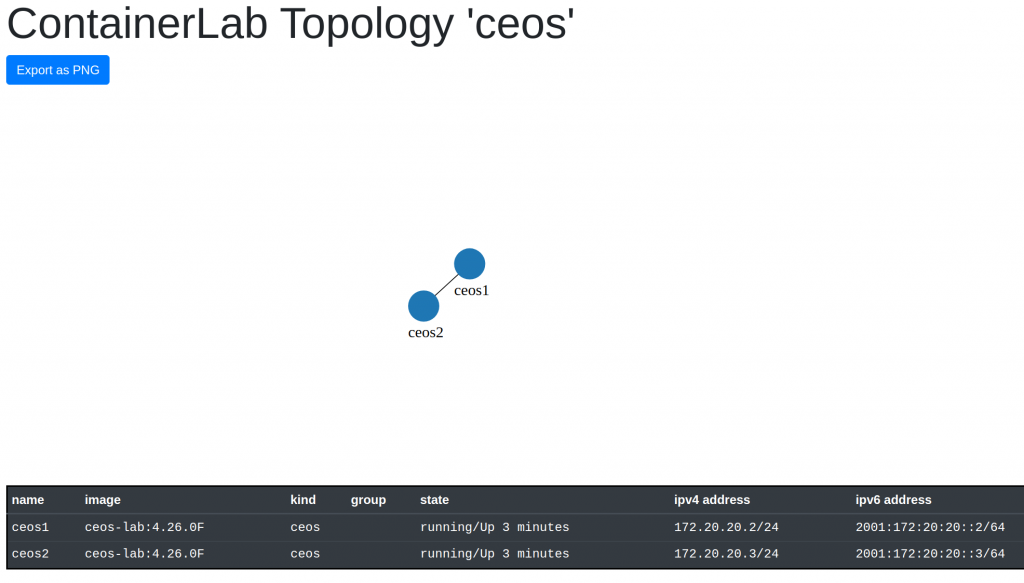
+---+-----------------+--------------+------------------+------+-------+---------+----------------+----------------------+
| # | Name | Container ID | Image | Kind | Group | State | IPv4 Address | IPv6 Address |
+---+-----------------+--------------+------------------+------+-------+---------+----------------+----------------------+
| 1 | clab-ceos-ceos1 | 2807cd2f689f | ceos-lab:4.26.0F | ceos | | running | 172.20.20.2/24 | 2001:172:20:20::2/64 |
| 2 | clab-ceos-ceos2 | e5d2aa4578b5 | ceos-lab:4.26.0F | ceos | | running | 172.20.20.3/24 | 2001:172:20:20::3/64 |
+---+-----------------+--------------+------------------+------+-------+---------+----------------+----------------------+
$ sudo clab graph -t ceos-lab1.yaml
INFO[0000] Parsing & checking topology file: ceos-lab1.yaml
INFO[0000] Listening on :50080...
After a bit, it seems it worked! And learned about an option to show a graph of your topology with “graph”
I checked the ceos container logs
$ docker logs clab-ceos-ceos1
....
[  OK  ] Started SYSV: Eos system init scrip...uns after POST, before ProcMgr).
         Starting Power-On Self Test...
         Starting EOS Warmup Service...
[  OK  ] Started Power-On Self Test.
[  OK  ] Reached target EOS regular mode.
[  OK  ] Started EOS Diagnostic Mode.
[     *] A start job is running for EOS Warmup Service (2min 9s / no limit)Reloading.
$
$ docker exec -it clab-ceos-ceos1 Cli
ceos1>
ceos1>enable
ceos1#show version
 cEOSLab
Hardware version:
Serial number:
Hardware MAC address: 001c.7389.2099
System MAC address: 001c.7389.2099

Software image version: 4.26.0F-21792469.4260F (engineering build)
Architecture: i686
Internal build version: 4.26.0F-21792469.4260F
Internal build ID: c5b41f65-54cd-44b1-b576-b5c48700ee19

cEOS tools version: 1.1
Kernel version: 5.10.0-8-amd64

Uptime: 0 minutes
Total memory: 8049260 kB
Free memory: 2469328 kB

ceos1#
ceos1#show interfaces description
Interface                      Status         Protocol           Description
Et1                            up             up
Ma0                            up             up
ceos1#show running-config interfaces ethernet 1
interface Ethernet1
ceos1#
Yes! Finally working!
So now, I dont have excuses to keep learning new things!
BTW, these are the different versions I am using at the moment:
I have read BGP churn before, I find the meaning and then forget about it until next time.
BGP churn = the rate of routing updates that BGP routers must process.
And I can’t really find a straight definition.
As well, I didnt know the actual meaning of churn was. So it s a machine to produce butter and the amount of customer stopping using a product.
I read at work something about AIGP from a different department. I searched and found that is a new BGP optional non-transitive path attribute and the BGP decision process is updated for that. And this is from 2015!!! So I am 6 years behind…. And there is a RFC7311
Note: BGP routers that do not support the optional non-transitive attributes (e.g. AIGP) must delete such attributes and must not pass them to other BGP peers.
So it seems a good feature if you run a big AS and want BGP to take into account the IGP cost.
Again, I am following the author post but adapting it to my environment using libvirt instead of VirtualBox and Debian10 as VM. All my data is here.
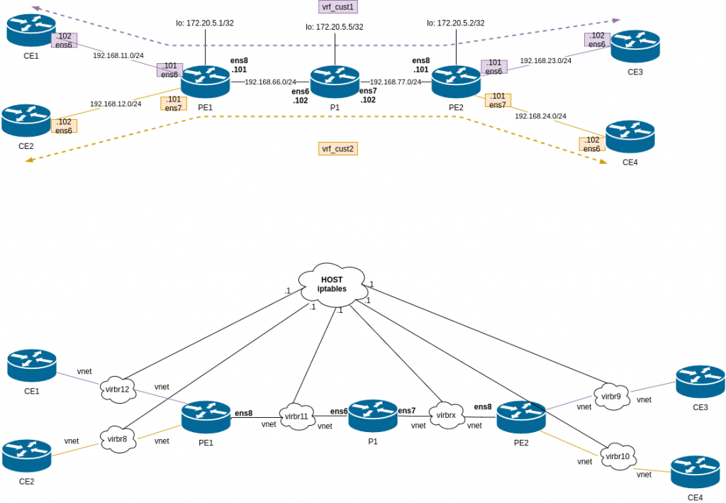
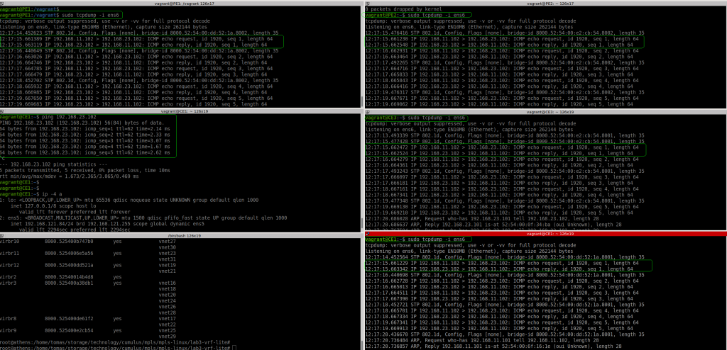
This is the diagram for the lab:
Difference from lab3 and lab2. We have P1, that is a pure P router, only handling labels, it doesnt do any BGP.
This time all devices FRR config are generated automatically via gen_frr_config.py (in lab2 all config was manual).
Again the environment is configured via Vagrant file + l3vpn_provisioning script. This is mix of lab2 (install FRR), lab3 (define VRFs) and lab1 (configure MPLS at linux level).
So after some tuning, everything is installed, routing looks correct (although I dont know why but I have to reload FRR to get the proper generated BGP config in PE1 and PE2. P1 is fine).
So let’s see PE1:
IGP (IS-IS) is up:
PE1# show isis neighbor
 Area ISIS:
   System Id           Interface   L  State        Holdtime SNPA
   P1                  ens8        2  Up            30       2020.2020.2020
 PE1#
 PE1# exit
 root@PE1:/home/vagrant#
BGP is up to PE2 and we can see routes received in AF IPv4VPN:
PE1#
 PE1# show bgp summary
 IPv4 Unicast Summary:
 BGP router identifier 172.20.5.1, local AS number 65010 vrf-id 0
 BGP table version 0
 RIB entries 0, using 0 bytes of memory
 Peers 1, using 21 KiB of memory
 Neighbor        V         AS   MsgRcvd   MsgSent   TblVer  InQ OutQ  Up/Down State/PfxRcd   PfxSnt
 172.20.5.2      4      65010       111       105        0    0    0 01:39:14            0        0
 Total number of neighbors 1
 IPv4 VPN Summary:
 BGP router identifier 172.20.5.1, local AS number 65010 vrf-id 0
 BGP table version 0
 RIB entries 11, using 2112 bytes of memory
 Peers 1, using 21 KiB of memory
 Neighbor        V         AS   MsgRcvd   MsgSent   TblVer  InQ OutQ  Up/Down State/PfxRcd   PfxSnt
 172.20.5.2      4      65010       111       105        0    0    0 01:39:14            2        2
 Total number of neighbors 1
 PE1#
Check routing tables, we can see prefixes in both VRFs, so that’s good. And the labels needed.
PE1# show ip route vrf all
 Codes: K - kernel route, C - connected, S - static, R - RIP,
        O - OSPF, I - IS-IS, B - BGP, E - EIGRP, N - NHRP,
        T - Table, v - VNC, V - VNC-Direct, A - Babel, D - SHARP,
        F - PBR, f - OpenFabric,
        > - selected route, * - FIB route, q - queued, r - rejected, b - backup
 VRF default:
 C>* 172.20.5.1/32 is directly connected, lo, 02:19:16
 I>* 172.20.5.2/32 [115/30] via 192.168.66.102, ens8, label 17, weight 1, 02:16:10
 I>* 172.20.5.5/32 [115/20] via 192.168.66.102, ens8, label implicit-null, weight 1, 02:18:34
 I   192.168.66.0/24 [115/20] via 192.168.66.102, ens8 inactive, weight 1, 02:18:34
 C>* 192.168.66.0/24 is directly connected, ens8, 02:19:16
 I>* 192.168.77.0/24 [115/20] via 192.168.66.102, ens8, label implicit-null, weight 1, 02:18:34
 C>* 192.168.121.0/24 is directly connected, ens5, 02:19:16
 K>* 192.168.121.1/32 [0/1024] is directly connected, ens5, 02:19:16
 VRF vrf_cust1:
 C>* 192.168.11.0/24 is directly connected, ens6, 02:19:05
 B>  192.168.23.0/24 [200/0] via 172.20.5.2 (vrf default) (recursive), label 80, weight 1, 02:13:32
 via 192.168.66.102, ens8 (vrf default), label 17/80, weight 1, 02:13:32
 VRF vrf_cust2:
 C>* 192.168.12.0/24 is directly connected, ens7, 02:19:05
 B>  192.168.24.0/24 [200/0] via 172.20.5.2 (vrf default) (recursive), label 81, weight 1, 02:13:32
 via 192.168.66.102, ens8 (vrf default), label 17/81, weight 1, 02:13:32
 PE1#
Now check LDP and MPLS labels. Everything looks sane. We have LDP labels for P1 (17) and PE2 (18). And labels for each VFR.
PE1# show mpls table
Inbound Label Type Nexthop Outbound Label
16 LDP 192.168.66.102 implicit-null
17 LDP 192.168.66.102 implicit-null
18 LDP 192.168.66.102 17
80BGPvrf_cust1 -
81BGPvrf_cust2 -
PE1#
PE1# show mpls ldp neighbor
AF ID State Remote Address Uptime
ipv4 172.20.5.5 OPERATIONAL 172.20.5.5 02:20:20
PE1#
PE1#
PE1# show mpls ldp binding
AF Destination Nexthop Local Label Remote Label In Use
ipv4 172.20.5.1/32 172.20.5.5 imp-null 16 no
ipv4 172.20.5.2/32 172.20.5.5 18 17 yes
ipv4 172.20.5.5/32 172.20.5.5 16 imp-null yes
ipv4 192.168.11.0/24 0.0.0.0 imp-null - no
ipv4 192.168.12.0/24 0.0.0.0 imp-null - no
ipv4 192.168.66.0/24 172.20.5.5 imp-null imp-null no
ipv4 192.168.77.0/24 172.20.5.5 17 imp-null yes
ipv4 192.168.121.0/24 172.20.5.5 imp-null imp-null no
PE1#
Similar view happens in PE2.
From P1 that is our P router. We only care about LDP and ISIS
P1#
 P1# show mpls table
  Inbound Label  Type  Nexthop         Outbound Label

 16             LDP   192.168.66.101  implicit-null
  17             LDP   192.168.77.101  implicit-null
 P1# show mpls ldp neighbor
 AF   ID              State       Remote Address    Uptime
 ipv4 172.20.5.1      OPERATIONAL 172.20.5.1      02:23:55
 ipv4 172.20.5.2      OPERATIONAL 172.20.5.2      02:21:01
 P1#
 P1# show isis neighbor
 Area ISIS:
   System Id           Interface   L  State        Holdtime SNPA
   PE1                 ens6        2  Up            28       2020.2020.2020
   PE2                 ens7        2  Up            29       2020.2020.2020
 P1#
 P1# show ip route
 Codes: K - kernel route, C - connected, S - static, R - RIP,
        O - OSPF, I - IS-IS, B - BGP, E - EIGRP, N - NHRP,
        T - Table, v - VNC, V - VNC-Direct, A - Babel, D - SHARP,
        F - PBR, f - OpenFabric,
        > - selected route, * - FIB route, q - queued, r - rejected, b - backup
 K>* 0.0.0.0/0 [0/1024] via 192.168.121.1, ens5, src 192.168.121.253, 02:24:45
 I>* 172.20.5.1/32 [115/20] via 192.168.66.101, ens6, label implicit-null, weight 1, 02:24:04
 I>* 172.20.5.2/32 [115/20] via 192.168.77.101, ens7, label implicit-null, weight 1, 02:21:39
 C>* 172.20.5.5/32 is directly connected, lo, 02:24:45
 I   192.168.66.0/24 [115/20] via 192.168.66.101, ens6 inactive, weight 1, 02:24:04
 C>* 192.168.66.0/24 is directly connected, ens6, 02:24:45
 I   192.168.77.0/24 [115/20] via 192.168.77.101, ens7 inactive, weight 1, 02:21:39
 C>* 192.168.77.0/24 is directly connected, ens7, 02:24:45
 C>* 192.168.121.0/24 is directly connected, ens5, 02:24:45
 K>* 192.168.121.1/32 [0/1024] is directly connected, ens5, 02:24:45
 P1#
So as usual, let’s try to test connectivity. Will ping from CE1 (connected to PE1) to CE3 (connected to PE2) that belong to the same VRF vrf_cust1.
First of all, I had to modify iptables in my host to avoid unnecessary NAT (iptables masquerade) between CE1 and CE3.
I have double-checked the configs. All routing and config looks sane in PE2:
vagrant@PE2:~$ ip route
 default via 192.168.121.1 dev ens5 proto dhcp src 192.168.121.31 metric 1024
 172.20.5.1  encap mpls  16 via 192.168.77.102 dev ens8 proto isis metric 20
 172.20.5.5 via 192.168.77.102 dev ens8 proto isis metric 20
 192.168.66.0/24 via 192.168.77.102 dev ens8 proto isis metric 20
 192.168.77.0/24 dev ens8 proto kernel scope link src 192.168.77.101
 192.168.121.0/24 dev ens5 proto kernel scope link src 192.168.121.31
 192.168.121.1 dev ens5 proto dhcp scope link src 192.168.121.31 metric 1024
 vagrant@PE2:~$
 vagrant@PE2:~$ ip -4 a
 1: lo:  mtu 65536 qdisc noqueue state UNKNOWN group default qlen 1000
     inet 127.0.0.1/8 scope host lo
        valid_lft forever preferred_lft forever
     inet 172.20.5.2/32 scope global lo
        valid_lft forever preferred_lft forever
 2: ens5:  mtu 1500 qdisc pfifo_fast state UP group default qlen 1000
     inet 192.168.121.31/24 brd 192.168.121.255 scope global dynamic ens5
        valid_lft 2524sec preferred_lft 2524sec
 3: ens6:  mtu 1500 qdisc pfifo_fast master vrf_cust1 state UP group default qlen 1000
     inet 192.168.23.101/24 brd 192.168.23.255 scope global ens6
        valid_lft forever preferred_lft forever
 4: ens7:  mtu 1500 qdisc pfifo_fast master vrf_cust2 state UP group default qlen 1000
     inet 192.168.24.101/24 brd 192.168.24.255 scope global ens7
        valid_lft forever preferred_lft forever
 5: ens8:  mtu 1500 qdisc pfifo_fast state UP group default qlen 1000
     inet 192.168.77.101/24 brd 192.168.77.255 scope global ens8
        valid_lft forever preferred_lft forever
 vagrant@PE2:~$
 vagrant@PE2:~$
 vagrant@PE2:~$
 vagrant@PE2:~$
 vagrant@PE2:~$ ip -M route
 16 as to 16 via inet 192.168.77.102 dev ens8 proto ldp
 17 via inet 192.168.77.102 dev ens8 proto ldp
 18 via inet 192.168.77.102 dev ens8 proto ldp
 vagrant@PE2:~$
 vagrant@PE2:~$ ip route show table 10
 blackhole default
 192.168.11.0/24  encap mpls  16/80 via 192.168.77.102 dev ens8 proto bgp metric 20
 broadcast 192.168.23.0 dev ens6 proto kernel scope link src 192.168.23.101
 192.168.23.0/24 dev ens6 proto kernel scope link src 192.168.23.101
 local 192.168.23.101 dev ens6 proto kernel scope host src 192.168.23.101
 broadcast 192.168.23.255 dev ens6 proto kernel scope link src 192.168.23.101
 vagrant@PE2:~$
 vagrant@PE2:~$
 vagrant@PE2:~$ ip vrf
 Name              Table
 vrf_cust1           10
 vrf_cust2           20
 vagrant@PE2:~$

root@PE2:/home/vagrant# sysctl -a | grep mpls
 net.mpls.conf.ens5.input = 0
 net.mpls.conf.ens6.input = 0
 net.mpls.conf.ens7.input = 0
 net.mpls.conf.ens8.input = 1
 net.mpls.conf.lo.input = 0
 net.mpls.conf.vrf_cust1.input = 0
 net.mpls.conf.vrf_cust2.input = 0
 net.mpls.default_ttl = 255
 net.mpls.ip_ttl_propagate = 1
 net.mpls.platform_labels = 100000
root@PE2:/home/vagrant#
root@PE2:/home/vagrant# lsmod | grep mpls
 mpls_iptunnel          16384  3
 mpls_router            36864  1 mpls_iptunnel
 ip_tunnel              24576  1 mpls_router
root@PE2:/home/vagrant#
So I am a bit puzzled the last couple of weeks about this issue. I was thinking that iptables was fooling me again and was dropping the traffic somehow but as far as I can see. PE2 is not sending anything and I dont really know how to troubleshoot FRR in this case. I have asked for help in the FRR list. Let’s see how it goes. I think I am doing something wrong because I am not doing anything new.
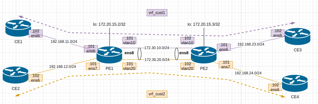
Again, I am following the author post but adapting it to my environment using libvirt instead of VirtualBox and Debian10 as VM. All my data is here.
This is the diagram adapted to my lab:
After updating Vagrantfile and provisioning script, I “vagrant up”. The 6 VMs dont take long to boot up so it is a good thing.
The provisioning script is mainly for configuration of PE1 and PE2 . This is a bit more detail:
    # enabling ipv4 forwarding (routing)
    sudo sysctl net.ipv4.ip_forward=1

    # add loopback (not used in lab3)
    sudo ip addr add 172.20.5.$self/32 dev lo

    # removing ip in link between pe1-pe2 as we will setup a trunk with two vlans.
    sudo ip addr del 192.168.66.10$self/24 dev ens8

    # creating two vlans 10 (ce1,ce3) and 20 (ce2, ce4)
    sudo ip link add link ens8 name vlan10 type vlan id 10
    sudo ip link add link ens8 name vlan20 type vlan id 20

    # assign IP to each vlan
    sudo ip addr add 172.30.10.10$self/24 dev vlan10
    sudo ip addr add 172.30.20.10$self/24 dev vlan20

    # turn up each vlan as by default are down
    sudo ip link set vlan10 up
    sudo ip link set vlan20 up

    # create two routing tables with a null route
    sudo ip route add blackhole 0.0.0.0/0 table 10
    sudo ip route add blackhole 0.0.0.0/0 table 20

    # create two VRFs and assign one table (created above) to each one
    sudo ip link add name vrf_cust1 type vrf table 10
    sudo ip link add name vrf_cust2 type vrf table 20

    # assign interfaces to the VRFs            // ie. PE1:
    sudo ip link set ens6 master vrf_cust1     // interface to CE1
    sudo ip link set vlan10 master vrf_cust1   // interface to PE2-vlan10

    sudo ip link set ens7 master vrf_cust2     // interface to CE2
    sudo ip link set vlan20 master vrf_cust2   // interface to PE2-vlan20

    # turn up VRFs
    sudo ip link set vrf_cust1 up
    sudo ip link set vrf_cust2 up

    # add static route in each VRF routing table to reach the opposite CE
    sudo ip route add 192.168.$route1.0/24 via 172.30.10.10$neighbor table 10
    sudo ip route add 192.168.$route2.0/24 via 172.30.20.10$neighbor table 20
Check the status of the VRFs in PE1:
vagrant@PE1:/vagrant$ ip link show type vrf
 8: vrf_cust1:  mtu 65536 qdisc noqueue state UP mode DEFAULT group default qlen 1000
     link/ether c6:b8:f2:3b:53:ed brd ff:ff:ff:ff:ff:ff
 9: vrf_cust2:  mtu 65536 qdisc noqueue state UP mode DEFAULT group default qlen 1000
     link/ether 62:1c:1d:0a:68:3d brd ff:ff:ff:ff:ff:ff
 vagrant@PE1:/vagrant$
 vagrant@PE1:/vagrant$ ip link show vrf vrf_cust1
 3: ens6:  mtu 1500 qdisc pfifo_fast master vrf_cust1 state UP mode DEFAULT group default qlen 1000
     link/ether 52:54:00:6f:16:1e brd ff:ff:ff:ff:ff:ff
 6: vlan10@ens8:  mtu 1500 qdisc noqueue master vrf_cust1 state UP mode DEFAULT group default qlen 1000
     link/ether 52:54:00:33:ab:0b brd ff:ff:ff:ff:ff:ff
 vagrant@PE1:/vagrant$
So let’s test if we can ping from CE1 to CE3:
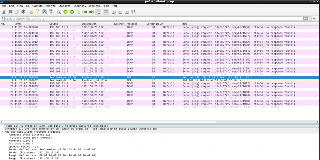
Ok, if fails. I noticed that PE1 sees the packet from CE1… but the source IP is not the expected one (11.1 is the host/my laptop). And the packet reaches to PE2 with the same wrong source IP and then to CE3. In CE3 the ICMP reply is sent to 11.1, to it never reaches CE1.
The positive thing is that VRF lite seems to work.
I double checked all IPs, routing, etc. duplicated MAC in CE1 and my laptop maybe??? I installed “net-tools” to get “arp” command and check the arp table contents in CE1. Checking the ARP request in wireshark, all was good.
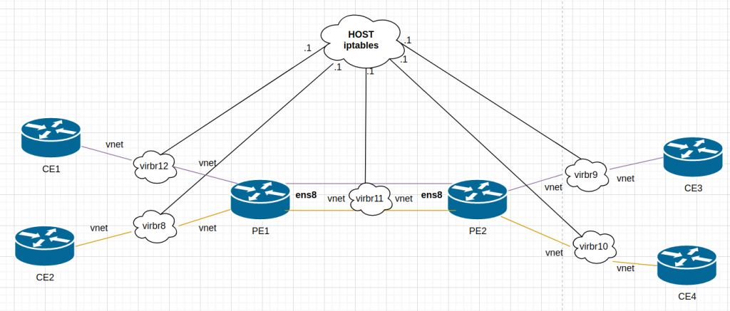
Somehow, the host was getting involved…. Keeping in mind that this is a simulated network, the host has access to all “links” in the lab. Libvirt creates a bridge (switch) for each link and it adds a vnet (port) for each VM that uses it:
“.1” is always the host but It was clear my routing was correct in all devices. I remembered that I had some issues during the summer when I was playing with containers/docker and doing some routing…. so I checked iptables….
I didnt have iptables in the VMs… but as stated earlier, the host is connected to all “links” used between the VMs. There is no real point-to-point link.
# iptables -t nat -vnL --line-numbers
...
Chain LIBVIRT_PRT (1 references)
num   pkts bytes target     prot opt in     out     source               destination
1       11   580 RETURN     all  --  *      *       192.168.11.0/24      224.0.0.0/24
2        0     0 RETURN     all  --  *      *       192.168.11.0/24      255.255.255.255
3        0     0 MASQUERADE  tcp  --  *      *       192.168.11.0/24     !192.168.11.0/24      masq ports: 1024-65535
4       40  7876 MASQUERADE  udp  --  *      *       192.168.11.0/24     !192.168.11.0/24      masq ports: 1024-65535
5       16  1344 MASQUERADE  all  --  *      *       192.168.11.0/24     !192.168.11.0/24
6       15   796 RETURN     all  --  *      *       192.168.24.0/24      224.0.0.0/24
7        0     0 RETURN     all  --  *      *       192.168.24.0/24      255.255.255.255
8        0     0 MASQUERADE  tcp  --  *      *       192.168.24.0/24     !192.168.24.0/24      masq ports: 1024-65535
9       49  9552 MASQUERADE  udp  --  *      *       192.168.24.0/24     !192.168.24.0/24      masq ports: 1024-65535
10       0     0 MASQUERADE  all  --  *      *       192.168.24.0/24     !192.168.24.0/24


# iptables-save -t nat
# Generated by iptables-save v1.8.7 on Sun Feb  7 12:06:09 2021
*nat
:PREROUTING ACCEPT [365:28580]
:INPUT ACCEPT [143:14556]
:OUTPUT ACCEPT [1617:160046]
:POSTROUTING ACCEPT [1390:101803]
:DOCKER - [0:0]
:LIBVIRT_PRT - [0:0]
-A PREROUTING -m addrtype --dst-type LOCAL -j DOCKER
-A OUTPUT ! -d 127.0.0.0/8 -m addrtype --dst-type LOCAL -j DOCKER
-A POSTROUTING -s 172.17.0.0/16 ! -o docker0 -j MASQUERADE
-A POSTROUTING -s 172.18.0.0/16 ! -o br-4bd17cfa19a8 -j MASQUERADE
-A POSTROUTING -s 172.19.0.0/16 ! -o br-43481af25965 -j MASQUERADE
-A POSTROUTING -j LIBVIRT_PRT
-A POSTROUTING -s 192.168.122.0/24 -d 224.0.0.0/24 -j RETURN
-A POSTROUTING -s 192.168.122.0/24 -d 255.255.255.255/32 -j RETURN
-A POSTROUTING -s 192.168.122.0/24 ! -d 192.168.122.0/24 -p tcp -j MASQUERADE --to-ports 1024-65535
-A POSTROUTING -s 192.168.122.0/24 ! -d 192.168.122.0/24 -p udp -j MASQUERADE --to-ports 1024-65535
-A POSTROUTING -s 192.168.122.0/24 ! -d 192.168.122.0/24 -j MASQUERADE
-A DOCKER -i docker0 -j RETURN
-A DOCKER -i br-4bd17cfa19a8 -j RETURN
-A DOCKER -i br-43481af25965 -j RETURN
-A LIBVIRT_PRT -s 192.168.11.0/24 -d 224.0.0.0/24 -j RETURN
-A LIBVIRT_PRT -s 192.168.11.0/24 -d 255.255.255.255/32 -j RETURN
-A LIBVIRT_PRT -s 192.168.11.0/24 ! -d 192.168.11.0/24 -p tcp -j MASQUERADE --to-ports 1024-65535
-A LIBVIRT_PRT -s 192.168.11.0/24 ! -d 192.168.11.0/24 -p udp -j MASQUERADE --to-ports 1024-65535
-A LIBVIRT_PRT -s 192.168.11.0/24 ! -d 192.168.11.0/24 -j MASQUERADE
-A LIBVIRT_PRT -s 192.168.24.0/24 -d 224.0.0.0/24 -j RETURN
-A LIBVIRT_PRT -s 192.168.24.0/24 -d 255.255.255.255/32 -j RETURN
-A LIBVIRT_PRT -s 192.168.24.0/24 ! -d 192.168.24.0/24 -p tcp -j MASQUERADE --to-ports 1024-65535
-A LIBVIRT_PRT -s 192.168.24.0/24 ! -d 192.168.24.0/24 -p udp -j MASQUERADE --to-ports 1024-65535
-A LIBVIRT_PRT -s 192.168.24.0/24 ! -d 192.168.24.0/24 -j MASQUERADE
Ok, it seems the traffic form 192.168.11.0 to 192.168.23.0 is NAT-ed (masquerade in iptables). So makes sense that I see the traffic as 11.1 in PE1. Let’s remove that:
Continuation of the first part, this time we want to establish dynamic LSP, so we will use LDP for label exchange and ISIS as IGP.
Again, I am following the author post but adapting it to my environment. The latest stable FRR is 7.5. All my data is here.
So once the routers R1, R2 and R3 are configured and FRR is reload (very important, restart doesnt do the trick). ISIS and LDP will come up, you need just need to be a bit patience.
Checking on R2, we can see ISIS and LDP established to R1 and R3 respectively. So this is a very good sign.
R2# show isis neighbor
 Area ISIS:
   System Id           Interface   L  State        Holdtime SNPA
   R1                  ens6        2  Up            30       2020.2020.2020
   R3                  ens7        2  Up            28       2020.2020.2020
 R2#
 R2# show mpls ldp neighbor
 AF   ID              State       Remote Address    Uptime
 ipv4 172.20.15.1     OPERATIONAL 172.20.15.1     00:27:44
 ipv4 172.20.15.3     OPERATIONAL 172.20.15.3     00:27:47
 R2#
Let’s check the routing table is programmed as expected. R2 is learning R1 and R3 loopbacks via ISIS and it reachable via MPLS (using implicit-null because R2 is doing Penultimate Hop Popping – PHP) based on the LDP bindings.
R2# show ip route
 Codes: K - kernel route, C - connected, S - static, R - RIP,
        O - OSPF, I - IS-IS, B - BGP, E - EIGRP, N - NHRP,
        T - Table, v - VNC, V - VNC-Direct, A - Babel, D - SHARP,
        F - PBR, f - OpenFabric,
        > - selected route, * - FIB route, q - queued, r - rejected, b - backup
 K>* 0.0.0.0/0 [0/1024] via 192.168.121.1, ens5, src 192.168.121.90, 00:12:42
 I>* 172.20.15.1/32 [115/20] via 192.168.12.101, ens6, label implicit-null, weight 1, 00:01:26
 C>* 172.20.15.2/32 is directly connected, lo, 00:12:42
 I>* 172.20.15.3/32 [115/20] via 192.168.23.101, ens7, label implicit-null, weight 1, 00:01:26
 I   192.168.12.0/24 [115/20] via 192.168.12.101, ens6 inactive, weight 1, 00:01:26
 C>* 192.168.12.0/24 is directly connected, ens6, 00:12:42
 I   192.168.23.0/24 [115/20] via 192.168.23.101, ens7 inactive, weight 1, 00:01:26
 C>* 192.168.23.0/24 is directly connected, ens7, 00:12:42
 C>* 192.168.121.0/24 is directly connected, ens5, 00:12:42
 K>* 192.168.121.1/32 [0/1024] is directly connected, ens5, 00:12:42
 R2#
R2# show mpls ldp binding
 AF   Destination          Nexthop         Local Label Remote Label  In Use
 ipv4 172.20.15.1/32       172.20.15.1     16          imp-null         yes
 ipv4 172.20.15.1/32       172.20.15.3     16          18                no
 ipv4 172.20.15.2/32       172.20.15.1     imp-null    16                no
 ipv4 172.20.15.2/32       172.20.15.3     imp-null    16                no
 ipv4 172.20.15.3/32       172.20.15.1     17          18                no
 ipv4 172.20.15.3/32       172.20.15.3     17          imp-null         yes
 ipv4 192.168.12.0/24      172.20.15.1     imp-null    imp-null          no
 ipv4 192.168.12.0/24      172.20.15.3     imp-null    17                no
 ipv4 192.168.23.0/24      172.20.15.1     imp-null    17                no
 ipv4 192.168.23.0/24      172.20.15.3     imp-null    imp-null          no
 ipv4 192.168.121.0/24     172.20.15.1     imp-null    imp-null          no
 ipv4 192.168.121.0/24     172.20.15.3     imp-null    imp-null          no
 R2#
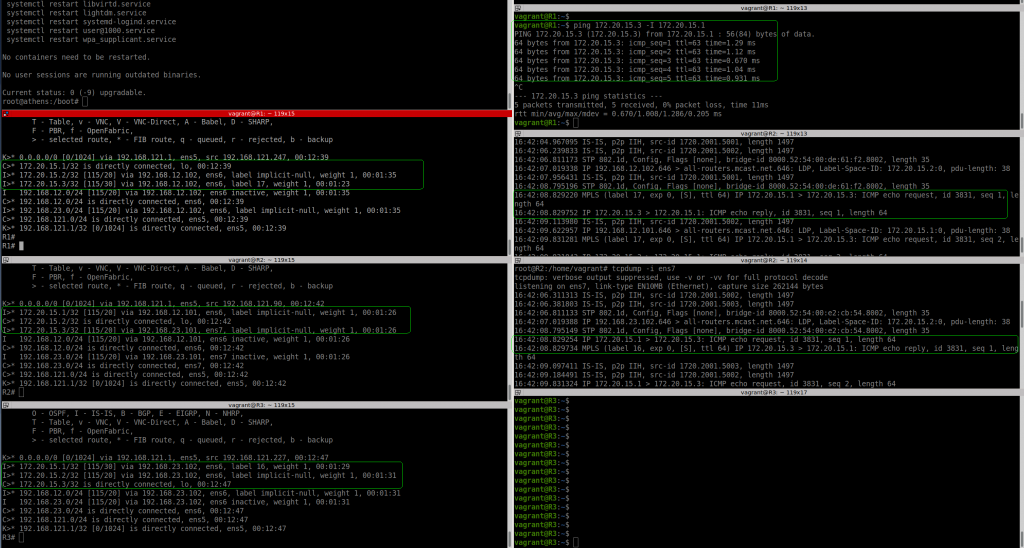
Now, let’s do the ping test and see if MPLS is actually used.
I can see clearly on the left hand side, that R2-ens6 (link to R1) is receiving the ICMP request as MPLS packet (label 17) and the ICMP reply is sent back to R1 without label (as expected by PHP). In R2-ens7 (link to R3) we see R2 sending the ICMP request without label (again expected due to PHP) and the ICMP reply from R3 is arriving with label 16 to R2.
I have to say that I had to try twice until things got working as expected. In my first attempt, somehow, R1 was not sending ICMP request to R2 encapsulated as MPLS packet, somehow the routing table was still programmed for only ISIS. Although ISIS, LDP and LDP bindings were correc.t
NOTES:
1- vagrant-nfs: I was thinking how to connect the VMs with my laptop for sharing files easily. It seems that by default the folder which is holding your Vagrant file is automatically exported in NFS in /vagrant in the VMs. Super handy. Just in case, a bit of documentation. My vagrant version is 2.2.14.
2- For loading the FRR config, I had to “lowercase” the VM hostname to match the FRR config file. Based on this link, it is quite easy. “${X,,}”
In November 2020, I got an email from the FRR email list about using MPLS with FRR. And the answer that you could do already natively (and easily) MPLS in Linux dumbfound me. So I add in my to-do list, try MPLS in Linux as per the blog. So all credits to the author, that’s a great job.
So reading the blog, I learned that the kernel supported MPLS since 4.3 (I am using 5.10) and creating VRF support was challenging until Cumulus did it. Thanks! So since April 2017 there is full support for L3VPNs in Linux… I’m getting a bit late in the wagon.
Anyway, I want to test myself and see if I can make it work. I downloaded the repo from the author to start working on it.
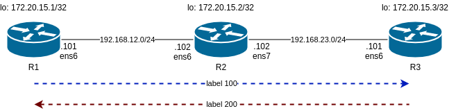
So I am following the same steps as him and will start with a lab consisting of static LSP. This is the diagram:
Main differences in my lab are:
1- I use libvirt instead of VirtualBox
2- I am using debian10 buster64 as VM
This affect the Vagrant file and the script to configure the static LSP. The libvirt_ commands I am using in Vagrantfile are ignored as I am not able to name the interfaces as I want. As well, I had to change the IP addressing as I had collisions with .1. And debian/buster64 has specific interfaces names that I have to use.
So, now we can turn up the lab.
/mpls-linux/lab1-static-lsps$ vagrant up
 Bringing machine 'r1' up with 'libvirt' provider…
 Bringing machine 'r2' up with 'libvirt' provider…
 Bringing machine 'r3' up with 'libvirt' provider…
 ==> r2: Checking if box 'debian/buster64' version '10.4.0' is up to date…
 ==> r3: Checking if box 'debian/buster64' version '10.4.0' is up to date…
 ==> r1: Checking if box 'debian/buster64' version '10.4.0' is up to date…
 ==> r1: Creating image (snapshot of base box volume).
 ==> r2: Creating image (snapshot of base box volume).
 ==> r3: Creating image (snapshot of base box volume).
 ==> r2: Creating domain with the following settings…
 ==> r1: Creating domain with the following settings…
...
/mpls-linux/lab1-static-lsps master$ vagrant status
 Current machine states:
 r1                        running (libvirt)
 r2                        running (libvirt)
 r3                        running (libvirt)
So we can check R1. One important detail here, is how we can defined a static route to reach R3 loopback and it is encapsulated in MPLS with label 100.
/mpls-linux/lab1-static-lsps$ vagrant ssh r1
...
vagrant@R1:~$ lsmod | grep mpls
 mpls_iptunnel          16384  1
 mpls_router            36864  1 mpls_iptunnel
 ip_tunnel              24576  1 mpls_router
 vagrant@R1:~$
 vagrant@R1:~$ ip route
 default via 192.168.121.1 dev ens5 proto dhcp src 192.168.121.124 metric 1024
 172.20.15.3  encap mpls  100 via 192.168.12.102 dev ens6
 192.168.12.0/24 dev ens6 proto kernel scope link src 192.168.12.101
 192.168.121.0/24 dev ens5 proto kernel scope link src 192.168.121.124
 192.168.121.1 dev ens5 proto dhcp scope link src 192.168.121.124 metric 1024
 vagrant@R1:~$
 vagrant@R1:~$ ip -4 a
 1: lo:  mtu 65536 qdisc noqueue state UNKNOWN group default qlen 1000
     inet 127.0.0.1/8 scope host lo
        valid_lft forever preferred_lft forever
     inet 172.20.15.1/32 scope global lo
        valid_lft forever preferred_lft forever
 2: ens5:  mtu 1500 qdisc pfifo_fast state UP group default qlen 1000
     inet 192.168.121.124/24 brd 192.168.121.255 scope global dynamic ens5
        valid_lft 3204sec preferred_lft 3204sec
 3: ens6:  mtu 1500 qdisc pfifo_fast state UP group default qlen 1000
     inet 192.168.12.101/24 brd 192.168.12.255 scope global ens6
        valid_lft forever preferred_lft forever
 vagrant@R1:~$
Now check R2 as it is our P router between R1 and R3 as per diagram. Important bit here is “ip -M route show”. This shows the MPLS routing label that is based in labels. In the standard “ip route” you dont seen any reference to MPLS.
vagrant@R2:~$ ip -4 a
 1: lo:  mtu 65536 qdisc noqueue state UNKNOWN group default qlen 1000
     inet 127.0.0.1/8 scope host lo
        valid_lft forever preferred_lft forever
     inet 172.20.15.2/32 scope global lo
        valid_lft forever preferred_lft forever
 2: ens5:  mtu 1500 qdisc pfifo_fast state UP group default qlen 1000
     inet 192.168.121.103/24 brd 192.168.121.255 scope global dynamic ens5
        valid_lft 2413sec preferred_lft 2413sec
 3: ens6:  mtu 1500 qdisc pfifo_fast state UP group default qlen 1000
     inet 192.168.12.102/24 brd 192.168.12.255 scope global ens6
        valid_lft forever preferred_lft forever
 4: ens7:  mtu 1500 qdisc pfifo_fast state UP group default qlen 1000
     inet 192.168.23.102/24 brd 192.168.23.255 scope global ens7
        valid_lft forever preferred_lft forever
 vagrant@R2:~$ ip route
 default via 192.168.121.1 dev ens5 proto dhcp src 192.168.121.103 metric 1024
 192.168.12.0/24 dev ens6 proto kernel scope link src 192.168.12.102
 192.168.23.0/24 dev ens7 proto kernel scope link src 192.168.23.102
 192.168.121.0/24 dev ens5 proto kernel scope link src 192.168.121.103
 192.168.121.1 dev ens5 proto dhcp scope link src 192.168.121.103 metric 1024
 vagrant@R2:~$
 vagrant@R2:~$ lsmod | grep mpls
 mpls_router            36864  0
 ip_tunnel              24576  1 mpls_router
 vagrant@R2:~$
 vagrant@R2:~$ ip -M route show
 100 via inet 192.168.23.101 dev ens7
 200 via inet 192.168.12.101 dev ens6
 vagrant@R2:~$
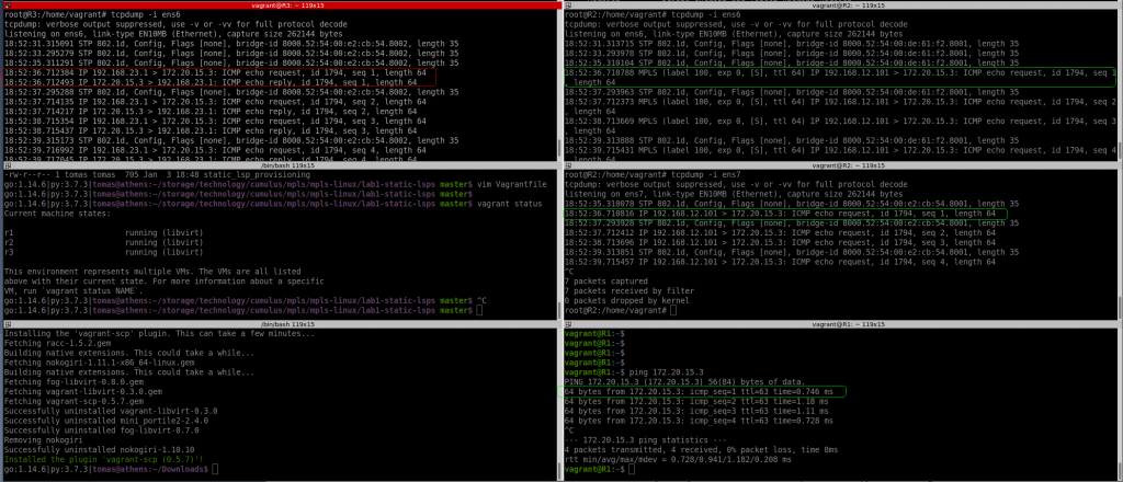
So let’s see if pinging the loopback in R1 and R3 gets labelled traffic:
I can see the labelled packet from R1 to R2 with label 100 as expected, but I dont see any “echo reply”…..
But ping is successful based on R1:
vagrant@R1:~$ ping 172.20.15.3
 PING 172.20.15.3 (172.20.15.3) 56(84) bytes of data.
 64 bytes from 172.20.15.3: icmp_seq=1 ttl=63 time=0.746 ms
 64 bytes from 172.20.15.3: icmp_seq=2 ttl=63 time=1.18 ms
 64 bytes from 172.20.15.3: icmp_seq=3 ttl=63 time=1.11 ms
 64 bytes from 172.20.15.3: icmp_seq=4 ttl=63 time=0.728 ms
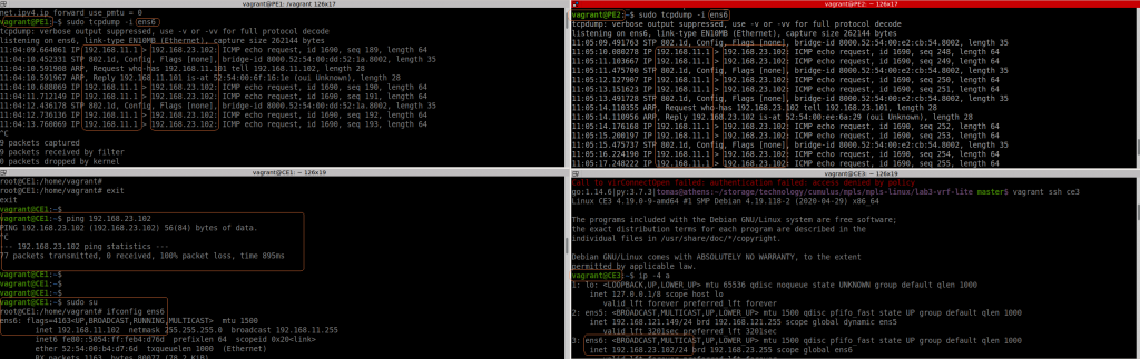
Something is wrong. As per pic below, with tcpdump in all interfaces, R3 is seeing the echo request from a different source (not R1).
And if I ping using R1 loopback, I can’t see anything leaving R1 ens6 interface.
vagrant@R1:~$ ping 172.20.15.3 -I lo
 PING 172.20.15.3 (172.20.15.3) from 172.20.15.1 lo: 56(84) bytes of data.
 ^C
 --- 172.20.15.3 ping statistics ---
 25 packets transmitted, 0 received, 100% packet loss, time 576ms
Based on the original blog post, this should work. The main difference here is I am using libvirt. Need to carry on investigating
This is my IP config, 23.1 is my laptop:
9: virbr3:  mtu 1500 qdisc noqueue state UP group default qlen 1000
     inet 192.168.121.1/24 brd 192.168.121.255 scope global virbr3
        valid_lft forever preferred_lft forever
 10: virbr8:  mtu 1500 qdisc noqueue state UP group default qlen 1000
     inet 192.168.12.1/24 brd 192.168.12.255 scope global virbr8
        valid_lft forever preferred_lft forever
 11: virbr9:  mtu 1500 qdisc noqueue state UP group default qlen 1000
     inet 192.168.23.1/24 brd 192.168.23.255 scope global virbr9
        valid_lft forever preferred_lft forever
How to ssh to a vagrant box without using “vagran ssh”: link
# save the config to a file
vagrant ssh-config > vagrant-ssh

# run ssh with the file
ssh -F vagrant-ssh default

# update your .gitignore for not tracking this file!!!!
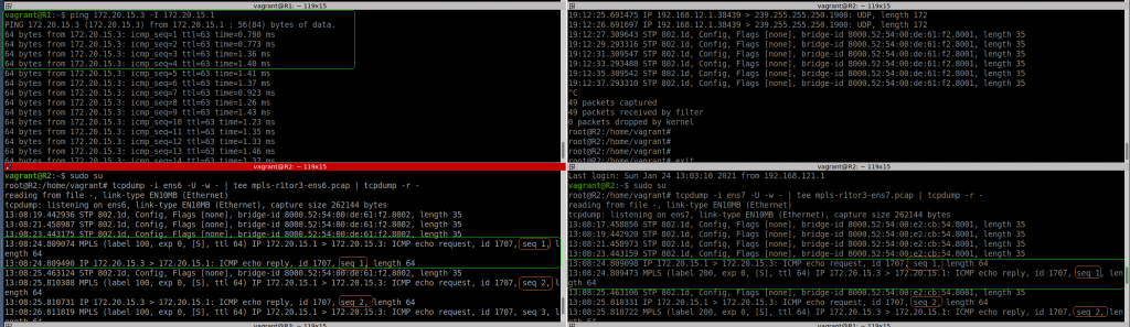
Ok, I have tried again. I rebooted my laptop, rebuilt the VMs, etc. And now it works
9: virbr3:  mtu 1500 qdisc noqueue state UP group default qlen 1000
     inet 192.168.121.1/24 brd 192.168.121.255 scope global virbr3
        valid_lft forever preferred_lft forever
 10: virbr8:  mtu 1500 qdisc noqueue state UP group default qlen 1000
     inet 192.168.12.1/24 brd 192.168.12.255 scope global virbr8
        valid_lft forever preferred_lft forever
 11: virbr9:  mtu 1500 qdisc noqueue state UP group default qlen 1000
     inet 192.168.23.1/24 brd 192.168.23.255 scope global virbr9
        valid_lft forever preferred_lft forever
 root@athens:/boot# uname -a
 Linux athens 5.9.0-5-amd64 #1 SMP Debian 5.9.15-1 (2020-12-17) x86_64 GNU/Linux
 root@athens:/boot#
I can see now clearly, how the ICMP request packet is encapsulated with MPLS tag 100 from R1 to R2 (ens6 interface), then the label is popped in R2, and you can see the same ICMP request leaving R2 via ens7 to R3.
Then the ICMP reply is encapsulated with MPLS tag 200 in R3 to R2 (ens7) and again, the labels is popped in R2, and you see the packet again from R2 (ens6) to R1.
So this test is successful at the end although not sure what I have been doing wrong before.
This is a very interesting blog entry from Cloudflare about PDU deployments in DCs and the theory behind. Nowadays nearly everything is cloud oriented. But we forget they still need to be deployed physically. In a old job, going dense in physical setups, requires more power and 3-phase PDUs where a must. The blog is quite good explaining the reasons to move to 3-phase and the challenges to balance the power. When you buy “colo”, you buy space and power, and that is not cheap.
This week I read that kubernetes is going to stop support for Docker soon. I was quite surprised. I am not an expert so it seems they have legit reasons. But I haven’t read anything from the other side. I think it is going to be painful so I need to try that in my lab and see how to do that migration. It has to be nice to learn that.
In the other end, I read a blog entry about ASICs from Cloudflare. I think without getting too technical it is a good one. And I learn about the different type of ASICs from Juniper. In the last years, I have only used devices powered by Broadcom ASICs. One day, I would like to try that P4/Barefoot Tofino devices. And related to this, I remember this NANOG presentation about ASICs that is really good (and fun!).