We have been able to create some nice MPLS labs using GNS3 and Cisco IOS. In my current employer, we use Arista so I wanted to create a lab environment with Arista kit to simulate a MPLS Segment Routing network. Keeping in mind that I try to run everything on my laptop, using GNS3 + Arista is not an option. You need to use the Arista vEOS image in GNS3 and it demands 2GB RAM per device and 1 CPU. In the past, I think I just managed to start two vEOS VMs before my laptop gave up. But Arista offers a version of EOS for containers.
So, what’s the difference between a virtual machine (VM) and a container? Well, searching the internet is going to give you many all answers. In my very simplify way:
- VM: needs an hypervisor to simulate hardware. It uses kernel and user space. It has a full OS. So it is like simulation a whole server/pc (imagine a standalone house)
- Container: runs in user space. Set of processes that are isolated from the rest of the system. Containers provide a way to virtualize an OS so that multiple workloads can run on a single OS instance (imagine an apartment in a building)
You just need to register in Arista web page to download a cEOS image.
Regarding MPLS Segment Routing (or SPRING for Juniper) it is an evolution of the standard MPLS, that was originally developed to improve the routing performance in core networks: avoid to make a routing look-ups per packet in core devices was very expensive in 80/90s (my very simplify way). MPLS started to being deployed around end 90s and became a defacto technology in all service providers. More info here.
Segment Routing is still based in labels, but adds improvements as it doesnt need a protocol for label exchange (one less thing to worry about). As well, it is based in “source routing” as the sources chooses the path and encodes it in the packet.
There are many sources in the internet that can explain MPLS SR better than me like all these:
https://www.segment-routing.net/tutorials/
As we are going to use Arista, I based my learning in these presentations:
https://ripe77.ripe.net/presentations/16-20181015-SegmentRouting.pdf
https://www.netnod.se/sites/default/files/2018-03/Peter%20Lundqvist_Arista_8.pdf
And reading more Arista docs.
All the code and how to build the lab is here:
https://github.com/thomarite/ceos-testing
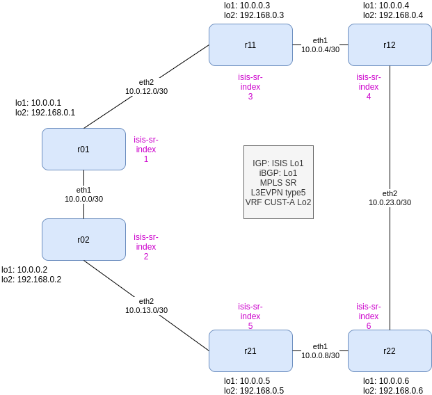
So what we need and what we are going to use in this lab:
- IPv4 (yeah, I should start working in IPv6…)
- IGP: we use ISIS
- Label Distribution: ISIS-SR
- BGP: using loobacks as best practices and using IGP for building a full-mesh
- L3/2VPN: EVPN
- All devices are PE
So let’s build the basic IP connectivity for r01:
!
hostname r01
!
interface Ethernet1
no switchport
ip address 10.0.10.1/30
!
interface Ethernet2
no switchport
ip address 10.0.12.1/30
!
interface Loopback1
description CORE Loopback
ip address 10.0.0.1/32
!
ip routing
!
Now let’s build our IGP with ISIS. We are going to use our Lo1 IP as network ID for each router. As well, we will keep it simple and define all routers as ISIS L2. We dont need anything fancy. We just want ISIS to build our iBGP peering. We will enable ISIS in the core interfaces (in this simple lab, all links and loopbacks)
!
router isis CORE
net 49.0000.0001.0010.0000.0000.0001.00  <-- BASED IN Lo1 !!!
is-type level-2
log-adjacency-changes
set-overload-bit on-startup wait-for-bgp timeout 180
!
interface Ethernet1
no switchport
ip address 10.0.10.1/30
isis enable CORE
isis metric 40
isis network point-to-point
!
interface Ethernet2
no switchport
ip address 10.0.12.1/30
isis enable CORE
isis metric 50
isis network point-to-point
!
interface Loopback1
description CORE Loopback
ip address 10.0.0.1/32
isis enable CORE
isis metric 1
!
It is seems there is a bug in the cEOS I am using as “show isis neighbors” fails but the routing is actually correct. Let’s see from r22:
r22#show ip route
VRF: default
Codes: C - connected, S - static, K - kernel,
O - OSPF, IA - OSPF inter area, E1 - OSPF external type 1,
E2 - OSPF external type 2, N1 - OSPF NSSA external type 1,
N2 - OSPF NSSA external type2, B - BGP, B I - iBGP, B E - eBGP,
R - RIP, I L1 - IS-IS level 1, I L2 - IS-IS level 2,
O3 - OSPFv3, A B - BGP Aggregate, A O - OSPF Summary,
NG - Nexthop Group Static Route, V - VXLAN Control Service,
DH - DHCP client installed default route, M - Martian,
DP - Dynamic Policy Route, L - VRF Leaked
Gateway of last resort is not set
I L2 10.0.0.1/32 [115/131] via 10.0.10.9, Ethernet1
I L2 10.0.0.2/32 [115/91] via 10.0.10.9, Ethernet1
I L2 10.0.0.3/32 [115/91] via 10.0.23.1, Ethernet2
I L2 10.0.0.4/32 [115/51] via 10.0.23.1, Ethernet2
I L2 10.0.0.5/32 [115/41] via 10.0.10.9, Ethernet1
C 10.0.0.6/32 is directly connected, Loopback1
I L2 10.0.10.0/30 [115/130] via 10.0.10.9, Ethernet1
I L2 10.0.10.4/30 [115/90] via 10.0.23.1, Ethernet2
C 10.0.10.8/30 is directly connected, Ethernet1
I L2 10.0.12.0/30 [115/140] via 10.0.23.1, Ethernet2
I L2 10.0.13.0/30 [115/90] via 10.0.10.9, Ethernet1
C 10.0.23.0/30 is directly connected, Ethernet2
r22#
r22# show logging
...
Log Buffer:
May 24 16:18:22 r22 SuperServer: %SYS-5-SYSTEM_RESTARTED: System restarted
May 24 16:24:29 r22 ConfigAgent: %SYS-5-CONFIG_E: Enter configuration mode from console by root on vty4 (UnknownIpAddr)
May 24 16:24:29 r22 ConfigAgent: %SYS-5-CONFIG_I: Configured from console by root on vty4 (UnknownIpAddr)
May 24 16:24:29 r22 ConfigAgent: %SYS-5-CONFIG_STARTUP: Startup config saved from system:/running-config by root on vty4 (UnknownIpAddr).
May 24 16:24:39 r22 Isis: %ISIS-4-ISIS_ADJCHG: L2 Neighbor State Change for SystemID 0000.0000.0004 on eth2 to UP
May 24 16:24:42 r22 Isis: %ISIS-4-ISIS_ADJCHG: L2 Neighbor State Change for SystemID 0000.0000.0005 on eth1 to UP
May 24 16:26:34 r22 ConfigAgent: %SYS-5-CONFIG_STARTUP: Startup config saved from system:/running-config by root on vty4 (UnknownIpAddr).
r22#
r22#show isis neighbors
% Internal error
% To see the details of this error, run the command 'show error 2'
Let’s build BGP, from r01 is like this:
!
router bgp 100
router-id 10.0.0.1
graceful-restart restart-time 300
graceful-restart
maximum-paths 2
neighbor AS100-CORE peer group
neighbor AS100-CORE remote-as 100
neighbor AS100-CORE next-hop-self
neighbor AS100-CORE update-source Loopback1
neighbor AS100-CORE timers 2 6
neighbor AS100-CORE additional-paths receive
neighbor AS100-CORE additional-paths send any
neighbor AS100-CORE password 7 Nmg+xbfVkywN7BBIllK5yw==
neighbor AS100-CORE send-community standard extended
neighbor AS100-CORE maximum-routes 0
neighbor 10.0.0.2 peer group AS100-CORE
neighbor 10.0.0.2 description R02
neighbor 10.0.0.3 peer group AS100-CORE
neighbor 10.0.0.3 description R11
neighbor 10.0.0.4 peer group AS100-CORE
neighbor 10.0.0.4 description R12
neighbor 10.0.0.5 peer group AS100-CORE
neighbor 10.0.0.5 description R21
neighbor 10.0.0.6 peer group AS100-CORE
neighbor 10.0.0.6 description R22
!
So once we have configured BGP in all routers, we should see a full mesh between all routers. This is from r22:
r22#show ip bgp summary
BGP summary information for VRF default
Router identifier 10.0.0.6, local AS number 100
Neighbor Status Codes: m - Under maintenance
Description Neighbor V AS MsgRcvd MsgSent InQ OutQ Up/Down State PfxRcd PfxAcc
R01 10.0.0.1 4 100 7 7 0 0 00:00:05 Estab 0 0
R02 10.0.0.2 4 100 7 7 0 0 00:00:05 Estab 0 0
R11 10.0.0.3 4 100 7 7 0 0 00:00:05 Estab 0 0
R12 10.0.0.4 4 100 6 7 0 0 00:00:04 Estab 0 0
R21 10.0.0.5 4 100 6 7 0 0 00:00:04 Estab 0 0
r22#
Now, enable MPLS and SR extension in ISIS:
!
mpls ip
!
mpls label range isis-sr 800000 65536
!
router isis CORE
  segment-routing mpls
    router-id 10.0.0.1  <-- based on Lo1 in each router
    no shutdown
!
interface Loopback1
  description CORE Loopback
  node-segment ipv4 index 1  <-- this has to be different in each node!!!
!
And you should see 5 ISIS-SR tunnels from each router. From r22:
r22#show isis segment-routing tunnel
Index Endpoint Nexthop Interface Labels TI-LFA
tunnel index

1 10.0.0.2/32 10.0.10.9 Ethernet1 [ 800002 ] -
2 10.0.0.3/32 10.0.23.1 Ethernet2 [ 800003 ] -
3 10.0.0.4/32 10.0.23.1 Ethernet2 [ 3 ] -
4 10.0.0.5/32 10.0.10.9 Ethernet1 [ 3 ] -
5 10.0.0.1/32 10.0.10.9 Ethernet1 [ 800001 ] -
r22#
As you can see above, the labels are based on the base index (800000) defined in the “mpls label range” command and the “node-segment index” defined in the loopback interface. So the label that identifies uniquely r01 is 800000 + 1 = 800001. The label “3” means you are a Penultime-Hop-P router and you remove the label to save a label look-up in the egress router.
Now, let’s configure EVPN for L2/L3VPN deployment in our MPLS network. From r01 should be:
!
service routing protocols model multi-agent --> you will have to reboot
!
router bgp 100
!
address-family evpn
neighbor default encapsulation mpls next-hop-self source-interface Loopback1
neighbor 10.0.0.2 activate
neighbor 10.0.0.3 activate
neighbor 10.0.0.4 activate
neighbor 10.0.0.5 activate
neighbor 10.0.0.6 activate
!
So once this is configured in all routers, we should see again a full mesh of EVPN BGP peers. From r12 this time:
r12#show bgp evpn summary
BGP summary information for VRF default
Router identifier 10.0.0.4, local AS number 100
Neighbor Status Codes: m - Under maintenance
Description Neighbor V AS MsgRcvd MsgSent InQ OutQ Up/Down State PfxRcd PfxAcc
R01 10.0.0.1 4 100 1254 1251 0 0 00:03:27 Estab 1 1
R02 10.0.0.2 4 100 1111 1107 0 0 00:03:27 Estab 1 1
R11 10.0.0.3 4 100 961 962 0 0 00:03:27 Estab 1 1
R21 10.0.0.5 4 100 884 888 0 0 00:03:27 Estab 1 1
R22 10.0.0.6 4 100 814 811 0 0 00:03:27 Estab 1 1
r12#
Now, let’s create a L3VPN with CUST-A vrf. We define it in all routers. For r01 should be:
!
vrf instance CUST-A
rd 100:1
!
interface Loopback2
vrf CUST-A
ip address 192.168.0.1/32   <-- each device has a unique one
!
ip routing vrf CUST-A
!
router bgp 100
!
vrf CUST-A
rd 100:1
route-target import evpn 100:1
route-target export evpn 100:1
network 192.168.0.1/32
Let’s see if the routing works from r12
r12# r12#show bgp evpn BGP routing table information for VRF default Router identifier 10.0.0.4, local AS number 100 Route status codes: s - suppressed, * - valid, > - active, # - not installed, E - ECMP head, e - ECMP S - Stale, c - Contributing to ECMP, b - backup % - Pending BGP convergence Origin codes: i - IGP, e - EGP, ? - incomplete AS Path Attributes: Or-ID - Originator ID, C-LST - Cluster List, LL Nexthop - Link Local NexthopNetwork Next Hop Metric LocPref Weight PathRD: 100:1 ip-prefix 192.168.0.1/32 10.0.0.1 - 100 0 iRD: 100:1 ip-prefix 192.168.0.2/32 10.0.0.2 - 100 0 iRD: 100:1 ip-prefix 192.168.0.3/32 10.0.0.3 - 100 0 iRD: 100:1 ip-prefix 192.168.0.5/32 10.0.0.5 - 100 0 iRD: 100:1 ip-prefix 192.168.0.6/32 10.0.0.6 - 100 0 ir12# r12#show ip route vrf CUST-A VRF: CUST-A Codes: C - connected, S - static, K - kernel, O - OSPF, IA - OSPF inter area, E1 - OSPF external type 1, E2 - OSPF external type 2, N1 - OSPF NSSA external type 1, N2 - OSPF NSSA external type2, B - BGP, B I - iBGP, B E - eBGP, R - RIP, I L1 - IS-IS level 1, I L2 - IS-IS level 2, O3 - OSPFv3, A B - BGP Aggregate, A O - OSPF Summary, NG - Nexthop Group Static Route, V - VXLAN Control Service, DH - DHCP client installed default route, M - Martian, DP - Dynamic Policy Route, L - VRF Leaked Gateway of last resort is not set B I 192.168.0.1/32 [200/0] via 10.0.0.1/32, IS-IS SR tunnel index 5, label 116384 via 10.0.10.5, Ethernet1, label 800001 B I 192.168.0.2/32 [200/0] via 10.0.0.2/32, IS-IS SR tunnel index 2, label 116384 via 10.0.10.5, Ethernet1, label 800002 B I 192.168.0.3/32 [200/0] via 10.0.0.3/32, IS-IS SR tunnel index 3, label 100000 via 10.0.10.5, Ethernet1, label imp-null(3) C 192.168.0.4/32 is directly connected, Loopback2 B I 192.168.0.5/32 [200/0] via 10.0.0.5/32, IS-IS SR tunnel index 4, label 116384 via 10.0.23.2, Ethernet2, label 800005 B I 192.168.0.6/32 [200/0] via 10.0.0.6/32, IS-IS SR tunnel index 1, label 116384 via 10.0.23.2, Ethernet2, label imp-null(3) r12#
So, all looks good. EVPN table shows all the prefixes for rd 100:1 and the routing table for CUST-A shows all Lo2 defined in each router.
BTW, I am not able to ping inside the VRF, I think it is something related to the broadcast of ARP:
UPDATE: Arista confirms that cEOS-lab doesn’t support MPLS dataplane. I need to use vEOS (vagrant). So that means I dont think my laptop has enough resources to build this lab in vEOS 🙁
r01#ping vrf CUST-A ip 192.168.0.6 interface loopback 2
PING 192.168.0.6 (192.168.0.6) from 192.168.0.1 lo2: 72(100) bytes of data.
--- 192.168.0.6 ping statistics ---
5 packets transmitted, 0 received, 100% packet loss, time 40ms
r01#

-- from other session in r01 --

r01#bash
bash-4.2# ip netns exec ns-CUST-A tcpdump -i lo2
tcpdump: verbose output suppressed, use -v or -vv for full protocol decode
listening on lo2, link-type EN10MB (Ethernet), capture size 262144 bytes
^C12:46:03.324918 02:00:00:00:00:00 (oui Unknown) > Broadcast, ethertype ARP (0x0806), length 42: Request who-has 192.168.0.6 tell 192.168.0.1, length 28
12:46:04.348750 02:00:00:00:00:00 (oui Unknown) > Broadcast, ethertype ARP (0x0806), length 42: Request who-has 192.168.0.6 tell 192.168.0.1, length 28
12:46:05.376723 02:00:00:00:00:00 (oui Unknown) > Broadcast, ethertype ARP (0x0806), length 42: Request who-has 192.168.0.6 tell 192.168.0.1, length 28
3 packets captured
3 packets received by filter
0 packets dropped by kernel
bash-4.2#

-- from other session in r22, we dont see anything --

r22#bash
bash-4.2# ip netns exec ns-CUST-A tcpdump -i lo2
tcpdump: verbose output suppressed, use -v or -vv for full protocol decode
listening on lo2, link-type EN10MB (Ethernet), capture size 262144 bytes
^C
0 packets captured
0 packets received by filter
0 packets dropped by kernel
bash-4.2#