As my last attempt to build a MPLS-SR Arista lab failed usin cEOS. I decided to try a different approach as I need more resources that my laptop has. For sometime, I wanted to use tesuto but I am not sure if it is still on business. From the main page, you can’t find any link to register (and pay) for the service. Although if you search for “pricing” you can find a link to that. That’s it.
The other option was to use EVE-NG. You can use it in your own bare-metal server or in the cloud.
So finally, I decided to spend some money. I signed up for GCP with a $300 free computing offer. So at least I dont pay for GCP yet and then I bought one year of EVE-NG professional. Let’s see how it goes.
Before buying the license, you need to install eve-ng. So I followed the official documentation to use it in GCP as it is quite up to date.
I consulted other links too just to compare other users experiences like these:
I had an issue during the process. When I had to configure DHCP, the IP wizard was showing garbage in the script. Hopefully I didnt have to add anything just accept all default values.
So once it is done, you need to https to the VM…. it didnt work. Somehow “apache” was started. So after startup, got access. I can login and change the default password.
root@eveng01:/var/www/html# service apache2 start
root@eveng01:/var/www/html# service apache2 status
So far, I am not planning to give it a static IP to the VM and a FQDN from my domain. Maybe in the future if I use it often.
Now, I need to create the Arista lab. I followed one of the links earlier, it was quite handy.
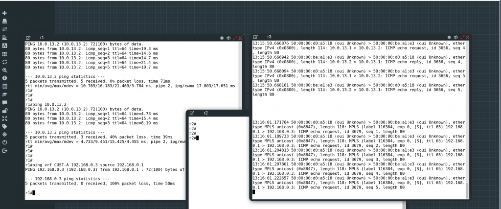
I created my small 3 nodes lab, apply the config. All this with a couple of reboots in each device and you have the lab up and running!
It is nice to work in a system with plenty of RAM. The VM has 60GB of RAM and 16vCPU. So I should be able to create a lab with 14 vEOS (each one needs 4GB and 1CPU).
$ top
top - 13:00:27 up 1:33, 1 user, load average: 2.12, 1.37, 1.04
Tasks: 266 total, 1 running, 168 sleeping, 0 stopped, 0 zombie
%Cpu(s): 10.3 us, 5.9 sy, 0.0 ni, 83.4 id, 0.0 wa, 0.0 hi, 0.4 si, 0.0 st
KiB Mem : 10.2/61838576 [ ]
KiB Swap: 0.0/0 [ ]
PID USER PR NI VIRT RES SHR S %CPU %MEM TIME+ COMMAND
27623 root 20 0 3034100 1.992g 25696 S 100.4 3.4 11:21.40 qemu-system-x86
26120 root 20 0 3034100 1.951g 26068 S 100.0 3.3 8:54.66 qemu-system-x86
24536 root 20 0 3034100 1.915g 26072 S 43.3 3.2 9:16.11 qemu-system-x86
245 root 25 5 0 0 0 S 8.2 0.0 2:05.36 uksmd
7500 www-data 20 0 377908 30744 12732 S 4.5 0.0 0:17.27 apache2
4262 root 20 0 1138416 15732 13508 S 0.8 0.0 0:25.40 janus
5526 tomcat8 20 0 5925452 348168 17676 S 0.8 0.6 0:43.17 java
159 root 20 0 0 0 0 I 0.4 0.0 0:01.13 kworker/6:1-eve
4363 mysql 20 0 2493932 85712 20408 S 0.4 0.1 0:10.80 mysqld
7210 www-data 20 0 377900 31024 12724 S 0.4 0.1 0:07.08 apache2
Unfortunately, I am hitting the same problem, and this time, the MAC addresses are the ones you expect to see based on the interface outputs:
I have asked again Arista if this is expected…
In the main time, I need to learn how to map the devices in the VM to external ports so I can access directly from my laptop.
UPDATE
My Arista SE confirmed that cEOS doesnt support MPLS Data Plane. And this should work with vEOS. So I asked in Arista forum about this problem with vEOS and turns out that this works but you need to be sure that a “physical” interface is attached to the VRF, a Loopback or SVI is not enough.
This seems to be the original post about the problem:
I have a supplier at my employer that requires to use a FTP server to send big files when you open a support ticket. For a long time (a couple of years) whenever I had to upload big files, I had to use my personal VM because my ftp connections failed from the office. I always blamed the super-smart firewall.
One day, I decided to fix the issue and allow the connection in our corporate firewall. I failed. Still couldnt upload files from the office. So keep using my personal VM.
This week I had to upload again a big file. This time I am working from home, so pretty much it is going to work the upload. Wrong! It fails. Ok, I checked a bit and got to the conclusion that it is my ISP or modem at home that is blocking FTP. Most ISP use CGN to stretch as much as possible the limited IPv4. I have IPv6 at home and my VM has IPv6 too… but the ftp server doesnt.
I checked the internet if there was any know issue with my ISP and FTP connections. No luck. I connected to my modem, nothing obvious messing around with FTP.
I decided to give it a proper go to this issue. I knew that it worked from my VM and it didnt from home. I noticed that I was running the same ftp client version in the VM and at home. So let’s debug the ftp client and take a packet capture in both locations.
CLI from the VM:
$ ftp -vd b.b.b.b
ftp: setsockopt: Bad file descriptor
Name: ftp
---> USER ftp
331 Please specify the password.
Password:
---> PASS XXXX
230 Login successful.
---> SYST
215 UNIX Type: L8
Remote system type is UNIX.
Using binary mode to transfer files.
ftp> cd support
---> CWD support
250 Directory successfully changed.
ftp> cd 211211
---> CWD 211211
250 Directory successfully changed.
ftp> put TEST.txt
local: TEST.txt remote: TEST.txt
---> TYPE I
200 Switching to Binary mode.
ftp: setsockopt (ignored): Permission denied
---> PORT a,a,a,a,162,57
200 PORT command successful. Consider using PASV.
---> STOR TEST.txt
150 Ok to send data.
226 Transfer complete.
28 bytes sent in 0.00 secs (854.4922 kB/s)
ftp> quit
---> QUIT
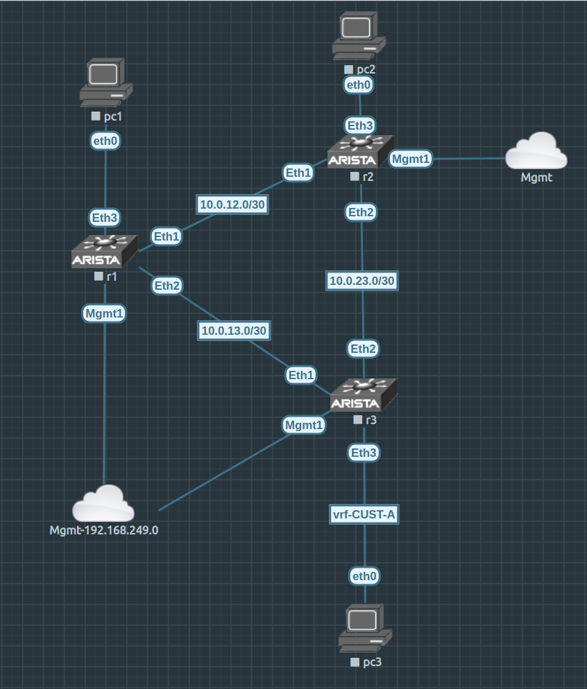
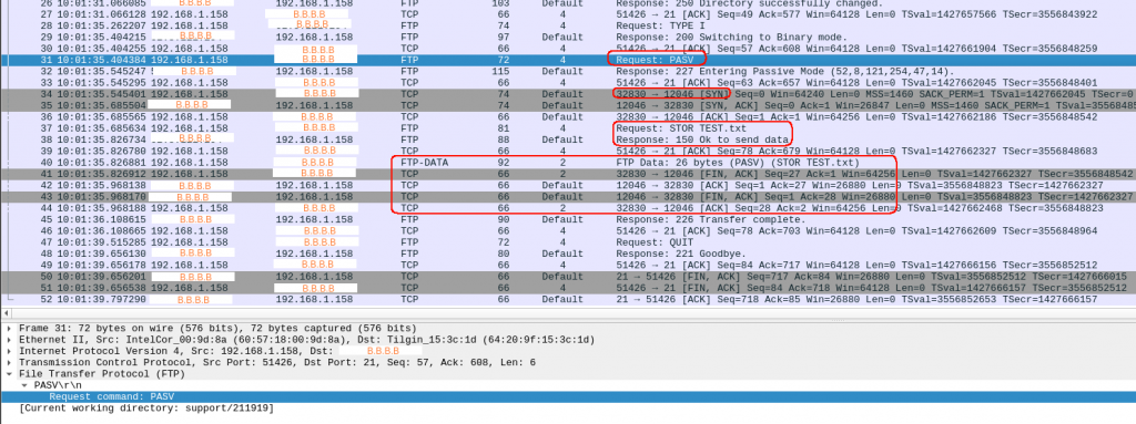
And this is the packet capture:
After typing “put” in packet 33, I see a “PASV” message from the server and a new connection (initiated by the server!) is established for the data transfer. All good.
So now, make the same from home and compare.
CLI from home without debug:
$ ftp b.b.b.b
Connected to b.b.b.b.
Name: ftp
331 Please specify the password.
Password:
230 Login successful.
Remote system type is UNIX.
Using binary mode to transfer files.
ftp> cd support
250 Directory successfully changed.
ftp> cd 211211
250 Directory successfully changed.
ftp> put TEST.txt
local: TEST.txt remote: TEST.txt
500 Illegal PORT command.
ftp: bind: Address already in use
ftp> quit
221 Goodbye.
CLI from home with debug:
$ ftp -vd b.b.b.b
ftp: setsockopt: Bad file descriptor
Name: ftp
---> USER ftp
331 Please specify the password.
Password:
---> PASS XXXX
230 Login successful.
---> SYST
215 UNIX Type: L8
Remote system type is UNIX.
Using binary mode to transfer files.
ftp> cd support
---> CWD support
250 Directory successfully changed.
ftp> cd 211211
---> CWD 211211
250 Directory successfully changed.
ftp> put TEST.txt
local: TEST.txt remote: TEST.txt
---> TYPE I
200 Switching to Binary mode.
ftp: setsockopt (ignored): Permission denied
---> PORT 192,168,1,158,202,145
500 Illegal PORT command.
ftp: bind: Address already in use
ftp> quit
---> QUIT
221 Goodbye.
So with and without debug I keep seeing “ftp: bind: Address already in use”…..
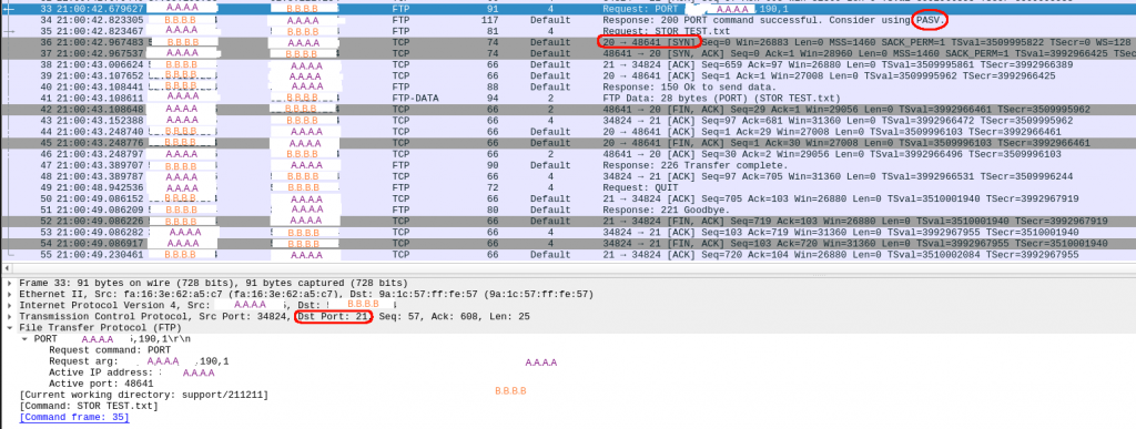
And this is the packet capture from home:
So after I type “put” in packet 32, the answer from the server is a “500”.
I wasnt clearly paying attention to the clues. I was still banging my head why the server was sending a “500 Ilegal PORT command”.
I was comparing both captures and both debug outputs… but still didnt it.
I thought I understood FTP. I knew that you use port TCP 21 to establish the control session and the data session / transfer is via new TCP session using a random port. That’s one of the reasons that using NAT or CGN can screw up your FTP sessions.
So I assumed that the issues wasnt my ISP. So it had to be my side (or me).
So finally, I decided to search for “ftp: bind: Address already in use” as it was the message that came up with and without debugging.
An entry from 2004…. it can’t fix my problem for sure…. keep reading and update from 2020… it says it works…. oh boy II
try using a passive connection with "ftp -p" instead, see if it helps...
There we go:
$ ftp -vdp b.b.b.b
ftp: setsockopt: Bad file descriptor
Name: ftp
---> USER ftp
331 Please specify the password.
Password:
---> PASS XXXX
230 Login successful.
---> SYST
215 UNIX Type: L8
Remote system type is UNIX.
Using binary mode to transfer files.
ftp> cd support
---> CWD support
250 Directory successfully changed.
ftp> cd 211211
---> CWD 211211
250 Directory successfully changed.
ftp> put TEST.txt
local: TEST.txt remote: TEST.txt
---> TYPE I
200 Switching to Binary mode.
ftp: setsockopt (ignored): Permission denied
---> PASV
227 Entering Passive Mode (b,b,b,b,46,248).
---> STOR TEST.txt
150 Ok to send data.
226 Transfer complete.
26 bytes sent in 0.00 secs (12.5386 kB/s)
ftp> quit
---> QUIT
221 Goodbye.
it worked !!!
I felt embarrassed. Time to search for FTP passive vs active…
Really good explanation. I hope I will never forget it.
FTP Active: The client issues a PORT command to the server signalling that it will “actively” provide an IP and port number so the server opens the Data Connection back to the client.
FTP Passive: The client issues a PASV command to indicate that it will wait “passively” for the server to supply an IP and port number, after which the client opens a Data Connection to the server.
So it worked in my VM because somehow the ftp server sent a PASV command (maybe because it detects there is no NAT as I have a public IP???).
From home, it failed because, by default, the connection is ftp active, so when the server tried to open the new data connection to me(something I couldnt see in the packet capture…) it failed as my ADSL modem wouldnt allow inbound connections.
Once I enabled “-p” in my connection to the server, all worked because it was me who started the new data connection and my firewall allows everything outbound.
Happy to solve the problem after a couple of years, and after a couple of hours of “serious” troubleshooting. It was shocking how blind I was. I had the ftp error message and the PASV from the trace.
This week I have been following a discussion in NANOG about LDPv6 (there are lot of emails but it is VERY interesting) and I realized that I didnt recognize the term “BGP-Free Core”. So I searched about it. It seems it wasnt an obscure subject and funny enough I have used that design in my MPLS labs in GNS3… So what is BGP-Free core? These are the links I read:
I am troubleshooting an issue in a docker setup with some Arista cEOS where I can’t ping inside a VRF. First I though it was a MTU issue as when you use MPLS, there is an extra tag in the L2 frame.
…But my pings weren’t that big.
Still wanted to increase the MTU because that’s the expected thing to do in your WAN links if you run MPLS and want your users in different VRFs to be able to use the full 1500 bytes.
After some searching, It seems you can change the default value using the config file as per this link:
$ ip link show docker0
9: docker0: mtu 1500 qdisc noqueue state DOWN mode DEFAULT group default
link/ether 02:42:be:73:8c:d3 brd ff:ff:ff:ff:ff:ff
$ cat /etc/docker/daemon.json
{
"data-root": "/home/somebody/storage/docker",
"mtu": 1600
}
$ sudo service docker restart
..
$ ip link show docker0
9: docker0: mtu 1500 qdisc noqueue state DOWN mode DEFAULT group default
link/ether 02:42:fb:c0:cf:a2 brd ff:ff:ff:ff:ff:ff
And restart docker. But still had mtu 1500. Checking another link it seems I actually need to create a container so the bridge come up with the new value
$ docker run -d busybox top
...
9: docker0: mtu 1600 qdisc noqueue state UP mode DEFAULT group default
link/ether 02:42:fb:c0:cf:a2 brd ff:ff:ff:ff:ff:ff
Funny thing, once I started my lab again (using docker-topo) still got MTU 1500!!!
Will have to dig a bit why docker-topo doesnt take the docker mtu 1600 from the config file.
Solution: docker-topo is creating user-defined bridges, so it needs to be told that the mtu is different. The “mtu:1600” in the docker config it is only for the default bridge so when you start the busybox, it is attached to the default bridge and you see 1600.
The other thing I was curious was if I could tcpdump the networks created by docker.
Yes, you can!
# docker network ls

# ifconfig

# tcpdump -i br-xxxx
We have been able to create some nice MPLS labs using GNS3 and Cisco IOS. In my current employer, we use Arista so I wanted to create a lab environment with Arista kit to simulate a MPLS Segment Routing network. Keeping in mind that I try to run everything on my laptop, using GNS3 + Arista is not an option. You need to use the Arista vEOS image in GNS3 and it demands 2GB RAM per device and 1 CPU. In the past, I think I just managed to start two vEOS VMs before my laptop gave up. But Arista offers a version of EOS for containers.
So, what’s the difference between a virtual machine (VM) and a container? Well, searching the internet is going to give you many all answers. In my very simplify way:
VM: needs an hypervisor to simulate hardware. It uses kernel and user space. It has a full OS. So it is like simulation a whole server/pc (imagine a standalone house)
Container: runs in user space. Set of processes that are isolated from the rest of the system. Containers provide a way to virtualize an OS so that multiple workloads can run on a single OS instance (imagine an apartment in a building)
You just need to register in Arista web page to download a cEOS image.
Regarding MPLS Segment Routing (or SPRING for Juniper) it is an evolution of the standard MPLS, that was originally developed to improve the routing performance in core networks: avoid to make a routing look-ups per packet in core devices was very expensive in 80/90s (my very simplify way). MPLS started to being deployed around end 90s and became a defacto technology in all service providers. More info here.
Segment Routing is still based in labels, but adds improvements as it doesnt need a protocol for label exchange (one less thing to worry about). As well, it is based in “source routing” as the sources chooses the path and encodes it in the packet.
There are many sources in the internet that can explain MPLS SR better than me like all these:
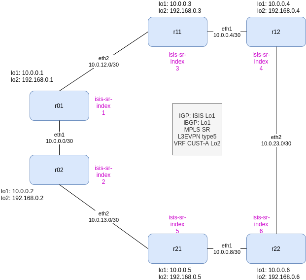
So what we need and what we are going to use in this lab:
IPv4 (yeah, I should start working in IPv6…)
IGP: we use ISIS
Label Distribution: ISIS-SR
BGP: using loobacks as best practices and using IGP for building a full-mesh
L3/2VPN: EVPN
All devices are PE
So let’s build the basic IP connectivity for r01:
!
hostname r01
!
interface Ethernet1
no switchport
ip address 10.0.10.1/30
!
interface Ethernet2
no switchport
ip address 10.0.12.1/30
!
interface Loopback1
description CORE Loopback
ip address 10.0.0.1/32
!
ip routing
!
Now let’s build our IGP with ISIS. We are going to use our Lo1 IP as network ID for each router. As well, we will keep it simple and define all routers as ISIS L2. We dont need anything fancy. We just want ISIS to build our iBGP peering. We will enable ISIS in the core interfaces (in this simple lab, all links and loopbacks)
!
router isis CORE
net 49.0000.0001.0010.0000.0000.0001.00  <-- BASED IN Lo1 !!!
is-type level-2
log-adjacency-changes
set-overload-bit on-startup wait-for-bgp timeout 180
!
interface Ethernet1
no switchport
ip address 10.0.10.1/30
isis enable CORE
isis metric 40
isis network point-to-point
!
interface Ethernet2
no switchport
ip address 10.0.12.1/30
isis enable CORE
isis metric 50
isis network point-to-point
!
interface Loopback1
description CORE Loopback
ip address 10.0.0.1/32
isis enable CORE
isis metric 1
!
It is seems there is a bug in the cEOS I am using as “show isis neighbors” fails but the routing is actually correct. Let’s see from r22:
r22#show ip route
VRF: default
Codes: C - connected, S - static, K - kernel,
O - OSPF, IA - OSPF inter area, E1 - OSPF external type 1,
E2 - OSPF external type 2, N1 - OSPF NSSA external type 1,
N2 - OSPF NSSA external type2, B - BGP, B I - iBGP, B E - eBGP,
R - RIP, I L1 - IS-IS level 1, I L2 - IS-IS level 2,
O3 - OSPFv3, A B - BGP Aggregate, A O - OSPF Summary,
NG - Nexthop Group Static Route, V - VXLAN Control Service,
DH - DHCP client installed default route, M - Martian,
DP - Dynamic Policy Route, L - VRF Leaked
Gateway of last resort is not set
I L2 10.0.0.1/32 [115/131] via 10.0.10.9, Ethernet1
I L2 10.0.0.2/32 [115/91] via 10.0.10.9, Ethernet1
I L2 10.0.0.3/32 [115/91] via 10.0.23.1, Ethernet2
I L2 10.0.0.4/32 [115/51] via 10.0.23.1, Ethernet2
I L2 10.0.0.5/32 [115/41] via 10.0.10.9, Ethernet1
C 10.0.0.6/32 is directly connected, Loopback1
I L2 10.0.10.0/30 [115/130] via 10.0.10.9, Ethernet1
I L2 10.0.10.4/30 [115/90] via 10.0.23.1, Ethernet2
C 10.0.10.8/30 is directly connected, Ethernet1
I L2 10.0.12.0/30 [115/140] via 10.0.23.1, Ethernet2
I L2 10.0.13.0/30 [115/90] via 10.0.10.9, Ethernet1
C 10.0.23.0/30 is directly connected, Ethernet2
r22#
r22# show logging
...
Log Buffer:
May 24 16:18:22 r22 SuperServer: %SYS-5-SYSTEM_RESTARTED: System restarted
May 24 16:24:29 r22 ConfigAgent: %SYS-5-CONFIG_E: Enter configuration mode from console by root on vty4 (UnknownIpAddr)
May 24 16:24:29 r22 ConfigAgent: %SYS-5-CONFIG_I: Configured from console by root on vty4 (UnknownIpAddr)
May 24 16:24:29 r22 ConfigAgent: %SYS-5-CONFIG_STARTUP: Startup config saved from system:/running-config by root on vty4 (UnknownIpAddr).
May 24 16:24:39 r22 Isis: %ISIS-4-ISIS_ADJCHG: L2 Neighbor State Change for SystemID 0000.0000.0004 on eth2 to UP
May 24 16:24:42 r22 Isis: %ISIS-4-ISIS_ADJCHG: L2 Neighbor State Change for SystemID 0000.0000.0005 on eth1 to UP
May 24 16:26:34 r22 ConfigAgent: %SYS-5-CONFIG_STARTUP: Startup config saved from system:/running-config by root on vty4 (UnknownIpAddr).
r22#
r22#show isis neighbors
% Internal error
% To see the details of this error, run the command 'show error 2'
So once we have configured BGP in all routers, we should see a full mesh between all routers. This is from r22:
r22#show ip bgp summary
BGP summary information for VRF default
Router identifier 10.0.0.6, local AS number 100
Neighbor Status Codes: m - Under maintenance
Description Neighbor V AS MsgRcvd MsgSent InQ OutQ Up/Down State PfxRcd PfxAcc
R01 10.0.0.1 4 100 7 7 0 0 00:00:05 Estab 0 0
R02 10.0.0.2 4 100 7 7 0 0 00:00:05 Estab 0 0
R11 10.0.0.3 4 100 7 7 0 0 00:00:05 Estab 0 0
R12 10.0.0.4 4 100 6 7 0 0 00:00:04 Estab 0 0
R21 10.0.0.5 4 100 6 7 0 0 00:00:04 Estab 0 0
r22#
Now, enable MPLS and SR extension in ISIS:
!
mpls ip
!
mpls label range isis-sr 800000 65536
!
router isis CORE
  segment-routing mpls
    router-id 10.0.0.1  <-- based on Lo1 in each router
    no shutdown
!
interface Loopback1
  description CORE Loopback
  node-segment ipv4 index 1  <-- this has to be different in each node!!!
!
And you should see 5 ISIS-SR tunnels from each router. From r22:
As you can see above, the labels are based on the base index (800000) defined in the “mpls label range” command and the “node-segment index” defined in the loopback interface. So the label that identifies uniquely r01 is 800000 + 1 = 800001. The label “3” means you are a Penultime-Hop-P router and you remove the label to save a label look-up in the egress router.
Now, let’s configure EVPN for L2/L3VPN deployment in our MPLS network. From r01 should be:
!
service routing protocols model multi-agent --> you will have to reboot
!
router bgp 100
!
address-family evpn
neighbor default encapsulation mpls next-hop-self source-interface Loopback1
neighbor 10.0.0.2 activate
neighbor 10.0.0.3 activate
neighbor 10.0.0.4 activate
neighbor 10.0.0.5 activate
neighbor 10.0.0.6 activate
!
So once this is configured in all routers, we should see again a full mesh of EVPN BGP peers. From r12 this time:
r12#show bgp evpn summary
BGP summary information for VRF default
Router identifier 10.0.0.4, local AS number 100
Neighbor Status Codes: m - Under maintenance
Description Neighbor V AS MsgRcvd MsgSent InQ OutQ Up/Down State PfxRcd PfxAcc
R01 10.0.0.1 4 100 1254 1251 0 0 00:03:27 Estab 1 1
R02 10.0.0.2 4 100 1111 1107 0 0 00:03:27 Estab 1 1
R11 10.0.0.3 4 100 961 962 0 0 00:03:27 Estab 1 1
R21 10.0.0.5 4 100 884 888 0 0 00:03:27 Estab 1 1
R22 10.0.0.6 4 100 814 811 0 0 00:03:27 Estab 1 1
r12#
Now, let’s create a L3VPN with CUST-A vrf. We define it in all routers. For r01 should be:
!
vrf instance CUST-A
rd 100:1
!
interface Loopback2
vrf CUST-A
ip address 192.168.0.1/32   <-- each device has a unique one
!
ip routing vrf CUST-A
!
router bgp 100
!
vrf CUST-A
rd 100:1
route-target import evpn 100:1
route-target export evpn 100:1
network 192.168.0.1/32
Let’s see if the routing works from r12
r12#
r12#show bgp evpn
BGP routing table information for VRF default
Router identifier 10.0.0.4, local AS number 100
Route status codes: s - suppressed, * - valid, > - active, # - not installed, E - ECMP head, e - ECMP
S - Stale, c - Contributing to ECMP, b - backup
% - Pending BGP convergence
Origin codes: i - IGP, e - EGP, ? - incomplete
AS Path Attributes: Or-ID - Originator ID, C-LST - Cluster List, LL Nexthop - Link Local Nexthop
Network Next Hop Metric LocPref Weight Path
RD: 100:1 ip-prefix 192.168.0.1/32 10.0.0.1 - 100 0 i
RD: 100:1 ip-prefix 192.168.0.2/32 10.0.0.2 - 100 0 i
RD: 100:1 ip-prefix 192.168.0.3/32 10.0.0.3 - 100 0 i
RD: 100:1 ip-prefix 192.168.0.5/32 10.0.0.5 - 100 0 i
RD: 100:1 ip-prefix 192.168.0.6/32 10.0.0.6 - 100 0 i
r12#
r12#show ip route vrf CUST-A
VRF: CUST-A
Codes: C - connected, S - static, K - kernel,
O - OSPF, IA - OSPF inter area, E1 - OSPF external type 1,
E2 - OSPF external type 2, N1 - OSPF NSSA external type 1,
N2 - OSPF NSSA external type2, B - BGP, B I - iBGP, B E - eBGP,
R - RIP, I L1 - IS-IS level 1, I L2 - IS-IS level 2,
O3 - OSPFv3, A B - BGP Aggregate, A O - OSPF Summary,
NG - Nexthop Group Static Route, V - VXLAN Control Service,
DH - DHCP client installed default route, M - Martian,
DP - Dynamic Policy Route, L - VRF Leaked
Gateway of last resort is not set
B I 192.168.0.1/32 [200/0] via 10.0.0.1/32, IS-IS SR tunnel index 5, label 116384
via 10.0.10.5, Ethernet1, label 800001
B I 192.168.0.2/32 [200/0] via 10.0.0.2/32, IS-IS SR tunnel index 2, label 116384
via 10.0.10.5, Ethernet1, label 800002
B I 192.168.0.3/32 [200/0] via 10.0.0.3/32, IS-IS SR tunnel index 3, label 100000
via 10.0.10.5, Ethernet1, label imp-null(3)
C 192.168.0.4/32 is directly connected, Loopback2
B I 192.168.0.5/32 [200/0] via 10.0.0.5/32, IS-IS SR tunnel index 4, label 116384
via 10.0.23.2, Ethernet2, label 800005
B I 192.168.0.6/32 [200/0] via 10.0.0.6/32, IS-IS SR tunnel index 1, label 116384
via 10.0.23.2, Ethernet2, label imp-null(3)
r12#
So, all looks good. EVPN table shows all the prefixes for rd 100:1 and the routing table for CUST-A shows all Lo2 defined in each router.
BTW, I am not able to ping inside the VRF, I think it is something related to the broadcast of ARP:
UPDATE: Arista confirms that cEOS-lab doesn’t support MPLS dataplane. I need to use vEOS (vagrant). So that means I dont think my laptop has enough resources to build this lab in vEOS 🙁
r01#ping vrf CUST-A ip 192.168.0.6 interface loopback 2
PING 192.168.0.6 (192.168.0.6) from 192.168.0.1 lo2: 72(100) bytes of data.
--- 192.168.0.6 ping statistics ---
5 packets transmitted, 0 received, 100% packet loss, time 40ms
r01#

-- from other session in r01 --

r01#bash
bash-4.2# ip netns exec ns-CUST-A tcpdump -i lo2
tcpdump: verbose output suppressed, use -v or -vv for full protocol decode
listening on lo2, link-type EN10MB (Ethernet), capture size 262144 bytes
^C12:46:03.324918 02:00:00:00:00:00 (oui Unknown) > Broadcast, ethertype ARP (0x0806), length 42: Request who-has 192.168.0.6 tell 192.168.0.1, length 28
12:46:04.348750 02:00:00:00:00:00 (oui Unknown) > Broadcast, ethertype ARP (0x0806), length 42: Request who-has 192.168.0.6 tell 192.168.0.1, length 28
12:46:05.376723 02:00:00:00:00:00 (oui Unknown) > Broadcast, ethertype ARP (0x0806), length 42: Request who-has 192.168.0.6 tell 192.168.0.1, length 28
3 packets captured
3 packets received by filter
0 packets dropped by kernel
bash-4.2#

-- from other session in r22, we dont see anything --

r22#bash
bash-4.2# ip netns exec ns-CUST-A tcpdump -i lo2
tcpdump: verbose output suppressed, use -v or -vv for full protocol decode
listening on lo2, link-type EN10MB (Ethernet), capture size 262144 bytes
^C
0 packets captured
0 packets received by filter
0 packets dropped by kernel
bash-4.2#
In a irc channel this week, one guy posted a link about visualization latency in a data center switching network .
And it was really good video for understanding how congestion happens inside the switch infrastructure and a very original idea to overcome this problem!
I tried to get a bit more info about the video and ended in the page of that paper:
I am not a researcher but the idea is quite original and it seems you dont need to re-invent the wheel. In the github repo even there is an example in P4. P4 is going to be big, and Barefoot has already commercial solutions about it with their tofino chip. Let’s see what Intel does with it…
Based on a continuation paper, it seems there is no much traction from the big cloud providers, and it surprises me, these guys have the muscle to make this kind of things. I always heard that hardware is very expensive to built and software is not. So there are few player willing to invest in new ideas. Everytime you hear about unicorn companies, nearly all of them are software companies.
And another paper says it needs more tuning/debugging.
I don’t know if it will successful in the future but I think it was interesting watching the video and reading about the concept.
This year, in my employer, I completed the migration to a MPLS SR Arista core network from a Brocade MPLS LDP one. Our backbone is still pure IPv4 so anything IPv6 is not going to be added. But this week, via an APNIC blog post I read about SRv6. And it looks quite interesting. So I went to the first post to go a bit deeper about what SRv6 is. Based on the statements of the blog, really big networks are already using this technology and quite a lot of support from the open source community too. I missed Arista in that list though.
So I tried to find some “real” proof of this SRv6 is some pcap files to see the format and get a bit better view. I could find at lest a source with some. The examples are not like the ones mentioned in the APNIC blog post but just for taking a look, it is enough:
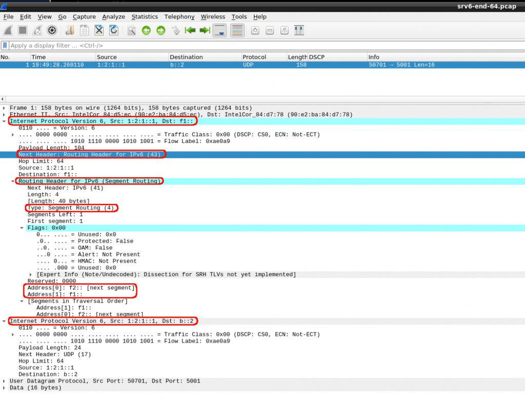
So I can see inside the IPv6 header, the SRv6 Header as defined in the rfc.
I dont really understand the second IPv6 header (Dst: b::2). From the first IPv6 header, the destination “f1::” has to be the first instruction SID1. I can see how it mentions it contains a SRH (Next Header: 43). And inside the routing header, we can see it is SR type (Type: 4). I assume that Address[0] and Address[1] are SID2 and SID3.
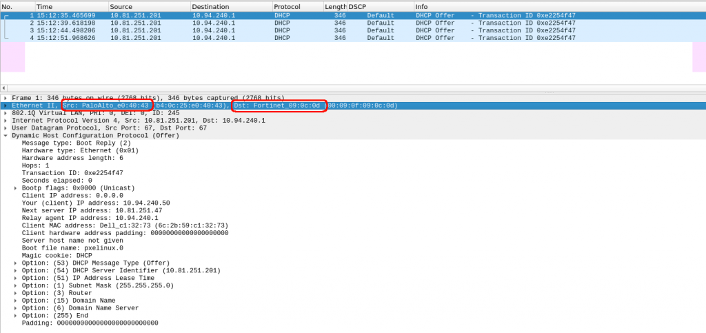
Today I have had “fun” troubleshooting an issue that looked easy at first sight. A colleague was trying to PXE boot some server from a network that we haven’t used for a while.
When the server boots up, asks for an IP via DHCP. As we have a centralized DHCP server infrastructure, we have configured DHCP relay in the firewall facing that server to send that request to the DHCP server.
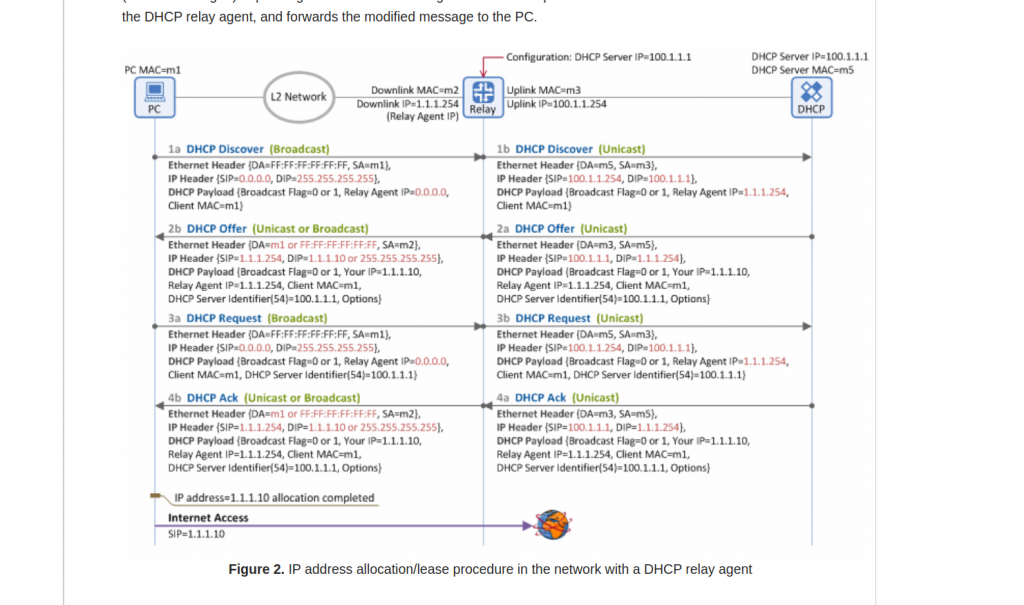
First, let’s take a look at how DHCP relay works. This is a very good link. And this diagram from the mentioned link it is really useful:
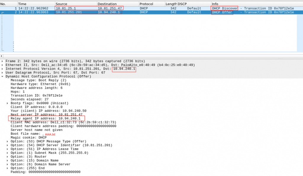
One think I learned is the reply (DCHP Offer) doesnt have to use as destination IP the same IP it received as source in DHCP Discover. In the picture, it is packet 2a.
Checking in our environment, we confirm that:
Our server is in 10.94.240.x network. Our firewall is acting as DHCP relay, and send the DHCP Discovery (unicast) to our VIP DHCP Server IP.
The DHCP offer, uses as source the physical IP of the DHCP server and destination is the DHCP relay IP (so it is 10.94.240.1 – the firewall IP in 10.94.240.x network)
Ok, so everything looks fine? No really. The server receives the query, it answers… but we dont see a DCHP Request/ACK.
BTW, keep in mind that DHCP is UDP….
So, we need to see where the packets are lost.
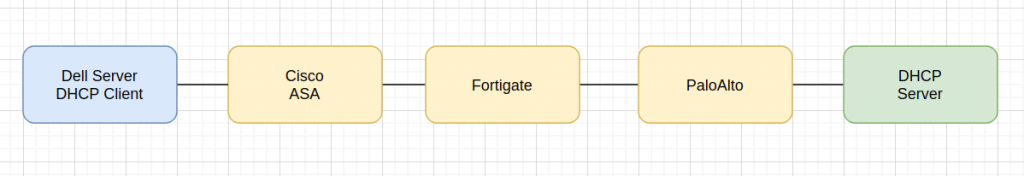
This is a high level path flow between the client and server:
So we need to check this connection is three different firewall vendors….
The initial troubleshooting was just using the GUI tools from Palo/Fortigate. We couldn see anything…. but the server was constantly receiving DHCP Discover and sending DHCP Offer… I dont get it:
# tcpdump -i X udp port 67 or 66 -nn

14:58:06.969462 IP 10.81.25.1.67 > 10.81.251.47.67: BOOTP/DHCP, Request from 6c:2b:59:c1:32:73, length 300
14:58:06.969564 IP 10.81.251.201.67 > 10.94.240.1.67: BOOTP/DHCP, Reply, length 300

14:58:28.329048 IP 10.81.25.1.67 > 10.81.251.47.67: BOOTP/DHCP, Request from 6c:2b:59:c1:32:73, length 300
14:58:28.329157 IP 10.81.251.201.67 > 10.94.240.1.67: BOOTP/DHCP, Reply, length 300
Initially it took me a while to see the request/reply because I was assuming the dhcp request had source 10.94.240.1. So I was seeing only the Reply but not the Request. That was when I went to clarify my head about DHCP Relay and found the link.
So ok, we have the DHCP Request/Reply, but absolutely nothing in the Palo. Is the palo dropping the packets or is forwarding? No idea. The GUI says nothing, I took a packet capture and couldnt see that traffic neither…
Doesnt makes sense.
Let’s get back to basic.
Did I mention DHCP is UDP? So how a next generation firewall (like paloalto) with all the fancy features enable (we have nearly all of them enable…) treats a UDP connection? UDP is stateless… but the firewall is statefull… the firewall creates a flow with the first packet so it can track, any new packet is considered part of that flow. But why we dont see the flows? We actually have only one flow. The firewall has created that session and offloaded to hardware. So you dont see anything else in the control-plane / GUI. The GUI only shows the end of a connection/flow. And as our flow DHCP Relay hasnt’ terminated (it is UDP) and the firewall keeps receiving packets, it is considered life (the firewall doesnt really know what is going on). So for that reason we dont see the connection in the PaloUI. Ok, I got to that point after a while…. I need to proof that the packet from the server is reaching the firewall and it is leaving it too.
How can I do that? Well, I need to delete that flow so the firewall considers a new connection and the tcpdump can see the packets.
This is the a good link from paloalto to take captures. So I found my connection and the cleared it:
palo(active)> show session all filter destination 10.94.240.1

ID Application State Type Flag Src[Sport]/Zone/Proto (translated IP[Port])
Vsys Dst[Dport]/Zone (translated IP[Port])
135493 dhcp ACTIVE FLOW 10.81.251.201[67]/ZONE1/17 (10.81.251.201[67])
vsys1 10.94.240.1[67]/ZONE2 (10.94.240.1[67])
palo(active)>
palo(active)> clear session id 135493
And now, my packet capture in paloalto confirms that it is sending the packet to the next firewall (checking the destination MAC) !!!
Ok, so we confirm the first firewall in the return path was fine…. next one, it is fortigate.
BTW, we were checked and assumed that the routing is fine in all routers, firewalls, etc. Sometimes is not the case… so when things dont follow your thoughts, get back to the very basics….
We have exactly the same issue as in PaloAlto. I can’t see anything in the logs about receiving a dhcp offer from palo and forwarding it to the last firewall Cisco.
And again, we apply the same reasoning. We have an UDP connection, we have a next-generation firewall (with fancy ASIC). And one more thing, in this fortigate firewall, we allow intra-zone traffic, so it is not going to show anyway in the GUI monitor…
Fantastic, we have confirmation that the second firewall receives and forwards the DHCP Reply!!!
Ok, now the last stop, Cisco ASA. This is an old firewall, I think it could be my father or Darth Vader.
I dont have the fancy tools for packet capture like Palo/Fortigate…. so I went to the basic “debug” commands and “packet-tracer”.
First, this was the dhcp config in Cisco:
vader/pri/act# show run | i dhcp
dhcprelay server 10.81.251.47 EGRESS
dhcprelay enable SERVERS-ZONE
dhcprelay timeout 60
And, the ACL allows all IP traffic in those interfaces… and couldnt see any deny in the logs.
So, I enabled all debugging things I could find for dhcp:
vader/pri/act# show debug
debug dhcpc detail enabled at level 1
debug dhcpc error enabled at level 1
debug dhcpc packet enabled at level 1
debug dhcpd packet enabled at level 1
debug dhcpd event enabled at level 1
debug dhcpd ddns enabled at level 1
debug dhcprelay error enabled at level 1
debug dhcprelay packet enabled at level 1
debug dhcprelay event enabled at level 200
vader/pri/act# DHCPD: Relay msg received, fip=ANY, fport=0 on SERVERS-ZONE interface
DHCPRA: relay binding found for client f48e.38c7.1b6e.
DHCPD: setting giaddr to 10.94.240.1.
dhcpd_forward_request: request from f48e.38c7.1b6e forwarded to 10.81.251.47.
DHCPD: Relay msg received, fip=ANY, fport=0 on SERVERS-ZONE interface
DHCPRA: relay binding found for client 6c2b.59c1.3273.
DHCPD: setting giaddr to 10.94.240.1.
dhcpd_forward_request: request from 6c2b.59c1.3273 forwarded to 10.81.251.47.
vader/pri/act#
So, the debugging doesnt says anything regarding the packet coming back from Fortigate… Not looking good I am afraid. I wasnt running out of ideas about debug commands. I coudn’t increase an log level neither….
Let’s give a go to packet tracer… doesnt looks good:
vader/pri/act# packet-tracer input EGRESS udp 10.81.251.201 67 10.94.240.1 67
Phase: 1
Type: ACCESS-LIST
Subtype:
Result: ALLOW
Config:
Implicit Rule
Additional Information:
MAC Access list
Phase: 2
Type: ACCESS-LIST
Subtype:
Result: DROP
Config:
Implicit Rule
Additional Information:
Result:
input-interface: EGRESS
input-status: up
input-line-status: up
Action: drop
Drop-reason: (acl-drop) Flow is denied by configured rule
So, we are sure our ACL is totally open but the firewall is dropping the packet coming from fortigate. Why? How to fix it?
Ok, get back to basics. Focus in Cisco config. It uses as DHCP relay server, 10.81.251.47 (VIP). But the DHCP reply is coming from the physical IP 10.81.251.201….. maybe Cisco doesnt like that…. Let’s try to add the physical IPs as a new DHCP server:
vader/pri/act# sri dhcp
dhcprelay server 10.81.251.47 EGRESS
dhcprelay server 10.81.251.201 EGRESS
dhcprelay server 10.81.251.202 EGRESS
I think I nearly cried after seeing this in the dhcp logs in our server:
May 12 16:16:27 dhcp1 dhcpd[2561]: DHCPDISCOVER from f4:8e:38:c7:1b:6e via 10.94.240.1
May 12 16:16:28 dhcp1 dhcpd[2561]: DHCPOFFER on 10.94.240.50 to f4:8e:38:c7:1b:6e (cmc-111) via 10.94.240.1
May 12 16:16:28 dhcp1 dhcpd[2561]: Wrote 0 class decls to leases file.
May 12 16:16:28 dhcp1 dhcpd[2561]: Wrote 0 deleted host decls to leases file.
May 12 16:16:28 dhcp1 dhcpd[2561]: Wrote 0 new dynamic host decls to leases file.
May 12 16:16:28 dhcp1 dhcpd[2561]: Wrote 1 leases to leases file.
May 12 16:16:28 dhcp1 dhcpd[2561]: DHCPREQUEST for 10.94.240.50 (10.81.251.202) from f4:8e:38:c7:1b:6e (cmc-111) via 10.94.240.1
May 12 16:16:28 dhcp1 dhcpd[2561]: DHCPACK on 10.94.240.50 to f4:8e:38:c7:1b:6e (cmc-111) via 10.94.240.1
So at the end, finally fixed…. it took too many hours.
Notes:
DHCP Realy: It is not that obvious the flow regarding IPs.
UDP and firewalls, debugging it is a bit more challenging.
Cisco ASA dhcprelay server IPs…. VIPs and non-VIPs please.
I read once about how to do load-balancing when using Route-Reflectors (RR) in a MPLS L3VPN network. It is a insteresting topic because RRs only reflect the best prefixes to the its clients. So how we make the RR to send more than one?
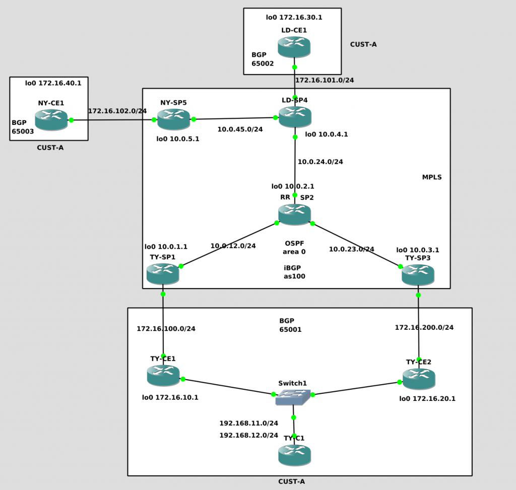
We have one customer vrf “CUST-A” with three locations: TY, LD and NY.
We are using BGP for PE-CE routing. Each site will use a different private ASN. Our SP is ASN 100.
TY has two connection to our SP so we want to make use of both of them.
We have a RR SP2 that is in line. So we need a full-mesh iBGP from all PE to SP2.
Our SP IGP is OSFP.
The goal is to make all other PE connected to CUST-A sites to be able to load-balance to TY site prefixes 192.168.11.0/24 and 192.168.12.0/24 using TY-SP1 and TY-SP3.
We start building the whole network as standard. This is very similar as stated in our first lab:
This is RR SP2 config:
!
ip vrf CUST-A
 rd 100:1
 route-target export 1:100
 route-target import 1:100
!
interface Loopback0
 ip address 10.0.2.1 255.255.255.255
!
interface GigabitEthernet1/0
 description to SP1-PE
 ip address 10.0.12.2 255.255.255.0
 negotiation auto
 mpls ip
!
interface GigabitEthernet2/0
 description to SP3-PE
 ip address 10.0.23.2 255.255.255.0
 negotiation auto
 mpls ip
!
interface FastEthernet3/0
 description TO-LD-SP4
 ip address 10.0.24.2 255.255.255.0
 duplex auto
 speed auto
 mpls ip
!
router ospf 1
 log-adjacency-changes
 network 10.0.2.0 0.0.0.255 area 0
 network 10.0.12.0 0.0.0.255 area 0
 network 10.0.23.0 0.0.0.255 area 0
 network 10.0.24.0 0.0.0.255 area 0
!
router bgp 100
 no synchronization
 bgp log-neighbor-changes
 neighbor 10.0.1.1 remote-as 100
 neighbor 10.0.1.1 update-source Loopback0
 neighbor 10.0.1.1 route-reflector-client
 neighbor 10.0.3.1 remote-as 100
 neighbor 10.0.3.1 update-source Loopback0
 neighbor 10.0.3.1 route-reflector-client
 neighbor 10.0.4.1 remote-as 100
 neighbor 10.0.4.1 update-source Loopback0
 neighbor 10.0.4.1 route-reflector-client
 neighbor 10.0.5.1 remote-as 100
 neighbor 10.0.5.1 update-source Loopback0
 neighbor 10.0.5.1 route-reflector-client
 no auto-summary
 !
 address-family vpnv4
  neighbor 10.0.1.1 activate
  neighbor 10.0.1.1 send-community both
  neighbor 10.0.1.1 route-reflector-client
  neighbor 10.0.3.1 activate
  neighbor 10.0.3.1 send-community both
  neighbor 10.0.3.1 route-reflector-client
  neighbor 10.0.4.1 activate
  neighbor 10.0.4.1 send-community both
  neighbor 10.0.4.1 route-reflector-client
  neighbor 10.0.5.1 activate
  neighbor 10.0.5.1 send-community both
  neighbor 10.0.5.1 route-reflector-client
 exit-address-family
 !
 address-family ipv4 vrf CUST-A
  no synchronization
 exit-address-family
!
!
mpls ldp router-id Loopback0 force
The configs for the SP PE follow the same patern, this is TY-SP1:
!
ip vrf CUST-A
 rd 100:1
 route-target export 1:100
 route-target import 1:100
!
interface Loopback0
 ip address 10.0.1.1 255.255.255.255
!
interface FastEthernet0/0
 description to HQ
 ip vrf forwarding CUST-A
 ip address 172.16.100.254 255.255.255.0
 duplex half
!
interface GigabitEthernet1/0
 description to SP2-P
 ip address 10.0.12.1 255.255.255.0
 negotiation auto
 mpls ip
!
router ospf 1
 log-adjacency-changes
 network 10.0.1.0 0.0.0.255 area 0
 network 10.0.12.0 0.0.0.255 area 0
!
router bgp 100
 no synchronization
 bgp log-neighbor-changes
 neighbor 10.0.2.1 remote-as 100
 neighbor 10.0.2.1 update-source Loopback0
 no auto-summary
 !
 address-family vpnv4
  neighbor 10.0.2.1 activate
  neighbor 10.0.2.1 send-community both
 exit-address-family
 !
 address-family ipv4 vrf CUST-A
  neighbor 172.16.100.1 remote-as 65001
  neighbor 172.16.100.1 activate
  neighbor 172.16.100.1 soft-reconfiguration inbound
  no synchronization
 exit-address-family
!
mpls ldp router-id Loopback0 force
!
Let’ see if LD-CE1 can ping our TY-C1
LD-CE1#traceroute 192.168.12.1 source 172.16.30.1

Type escape sequence to abort.
Tracing the route to 192.168.12.1

  1 172.16.101.254 8 msec 20 msec 8 msec
  2 10.0.24.2 [MPLS: Labels 18/23 Exp 0] 40 msec 40 msec 36 msec
  3 172.16.200.254 [MPLS: Label 23 Exp 0] 12 msec 32 msec 28 msec
  4 172.16.200.1 60 msec 40 msec 40 msec
  5 192.168.12.1 [AS 65001] 40 msec 60 msec 60 msec
LD-CE1#
LD-CE1#
LD-CE1#ping 192.168.11.1 source 172.16.30.1

Type escape sequence to abort.
Sending 5, 100-byte ICMP Echos to 192.168.11.1, timeout is 2 seconds:
Packet sent with a source address of 172.16.30.1
!!!!!
Success rate is 100 percent (5/5), round-trip min/avg/max = 44/54/72 ms
LD-CE1#
LD-CE1#
LD-CE1#
LD-CE1#sh
LD-CE1#show ip rou
LD-CE1#show ip route
Codes: C - connected, S - static, R - RIP, M - mobile, B - BGP
       D - EIGRP, EX - EIGRP external, O - OSPF, IA - OSPF inter area
       N1 - OSPF NSSA external type 1, N2 - OSPF NSSA external type 2
       E1 - OSPF external type 1, E2 - OSPF external type 2
       i - IS-IS, su - IS-IS summary, L1 - IS-IS level-1, L2 - IS-IS level-2
       ia - IS-IS inter area, * - candidate default, U - per-user static route
       o - ODR, P - periodic downloaded static route

Gateway of last resort is not set

B    192.168.12.0/24 [20/0] via 172.16.101.254, 01:19:31
     172.16.0.0/16 is variably subnetted, 2 subnets, 2 masks
C       172.16.30.1/32 is directly connected, Loopback0
C       172.16.101.0/24 is directly connected, FastEthernet0/0
B    192.168.11.0/24 [20/0] via 172.16.101.254, 01:19:31
LD-CE1#
So, what do we see when everything is configured?
From SP2-RR, we see all BGP peers up to PEs and in the vpnv4 table we can see the TY prefixes 192.168.11.0/24 and 192.168.12.0/24. But only the path from TY-SP1 is preferred….
SP2#show ip ospf neighbor

Neighbor ID     Pri   State           Dead Time   Address         Interface
10.0.4.1          1   FULL/DR         00:00:39    10.0.24.1       FastEthernet3/0
10.0.3.1          1   FULL/DR         00:00:39    10.0.23.1       GigabitEthernet2/0
10.0.1.1          1   FULL/BDR        00:00:37    10.0.12.1       GigabitEthernet1/0
SP2#
SP2#
SP2#show ip bgp summary
BGP router identifier 10.0.2.1, local AS number 100
BGP table version is 1, main routing table version 1

Neighbor        V          AS MsgRcvd MsgSent   TblVer  InQ OutQ Up/Down  State/PfxRcd
10.0.1.1        4        100      98     111        1    0    0 01:25:16        0
10.0.3.1        4        100      93     108        1    0    0 01:25:05        0
10.0.4.1        4        100      96     114        1    0    0 00:55:06        0
10.0.5.1        4        100      29      32        1    0    0 00:28:02        0
SP2#
SP2#show ip bgp vpnv4 all
BGP table version is 9, local router ID is 10.0.2.1
Status codes: s suppressed, d damped, h history, * valid, > best, i - internal,
              r RIB-failure, S Stale
Origin codes: i - IGP, e - EGP, ? - incomplete

   Network          Next Hop            Metric LocPrf Weight Path
Route Distinguisher: 100:1 (default for vrf CUST-A)
*>i172.16.30.1/32   10.0.4.1                 0    100      0 65002 i
*>i192.168.11.0     10.0.1.1                 0    100      0 65001 i
* i                 10.0.3.1                 0    100      0 65001 i
*>i192.168.12.0     10.0.1.1                 0    100      0 65001 i
* i                 10.0.3.1                 0    100      0 65001 i
SP2#
Let confirm that the PE only receive the best prefix from the RR. So, from LD-SP4, we can see the paths to TY 192.168.11/12 via TY-SP1 only:
LD-SP4#show ip bgp vpnv4 all
BGP table version is 18, local router ID is 10.0.4.1
Status codes: s suppressed, d damped, h history, * valid, > best, i - internal,
              r RIB-failure, S Stale
Origin codes: i - IGP, e - EGP, ? - incomplete

   Network          Next Hop            Metric LocPrf Weight Path
Route Distinguisher: 100:1 (default for vrf CUST-A)
*> 172.16.30.1/32   172.16.101.1             0             0 65002 i
*>i192.168.11.0     10.0.1.1                 0    100      0 65001 i
*>i192.168.12.0     10.0.1.1                 0    100      0 65001 i
LD-SP4#
How do we make RR-SP2 to learn and advertise TY-SP1 and TY-SP3 paths. We need to use different RD in TY-SP1/3 respectively.
We have RD 100:1 assigned to CUST-A in all PEs. We are going to change that in TY-SP1/3 so RR will see two different VPNv4 prefixes for the same destination.
Let’s change TY-SP1 RD 100:1 to 100:101 and TY-SP3 to 100:102. Watch out as all routing config related to VRF CUST-A will disappear.
And what about the RT config? Do we have to change anything? Actually, we need to keep it the same (we need to retype it), nothing changes here. Keep in mind that RT is used to import/export vpnv4 prefixes into the VRF. The RD is not used to import/export so for that reason (as we are going to see) we could actually use any RD for a VRF in a PE.
Let’s see the changes for TY-SP1:
TY-SP1(config)#ip vrf CUST-A
TY-SP1(config-vrf)#no rd 100:1
% "rd 100:1" for VRF CUST-A scheduled for deletion
TY-SP1(config-vrf)#
*Apr 27 22:28:48.347: %BGP-5-ADJCHANGE: neighbor 172.16.100.1 vpn vrf CUST-A Down Neighbor deleted
TY-SP1(config-vrf)#rd 100:101
% Deletion of "rd" in progress; wait for it to complete
TY-SP1(config-vrf)#
TY-SP1(config-vrf)#rd 100:101
TY-SP1(config-vrf)#route-target export 100:1
TY-SP1(config-vrf)#route-target import 100:1
TY-SP1(config-vrf)#exit
TY-SP1(config)#router bgp 100
TY-SP1(config-router)#address-family ipv4 vrf CUST-A
TY-SP1(config-router-af)#  neighbor 172.16.100.1 remote-as 65001
TY-SP1(config-router-af)#  neighbor 172.16.100.1 activate
TY-SP1(config-router-af)#  neighbor 172.16.100.1 soft-reconfiguration inbound
TY-SP1(config-router-af)#
*Apr 27 22:33:50.571: %BGP-5-ADJCHANGE: neighbor 172.16.100.1 vpn vrf CUST-A Up
TY-SP1(config-router-af)#
So after repeating the same step in TY-SP3 (using RD 100:102), let’s see what happens in RR-SP2:
SP2#show ip bgp vpnv4 all
BGP table version is 51, local router ID is 10.0.2.1
Status codes: s suppressed, d damped, h history, * valid, > best, i - internal,
              r RIB-failure, S Stale
Origin codes: i - IGP, e - EGP, ? - incomplete

   Network          Next Hop            Metric LocPrf Weight Path
Route Distinguisher: 100:1 (default for vrf CUST-A)
*>i172.16.30.1/32   10.0.4.1                 0    100      0 65002 i
* i192.168.11.0     10.0.3.1                 0    100      0 65001 i
*>i                 10.0.1.1                 0    100      0 65001 i
* i192.168.12.0     10.0.3.1                 0    100      0 65001 i
*>i                 10.0.1.1                 0    100      0 65001 i
Route Distinguisher: 100:101
*>i192.168.11.0     10.0.1.1                 0    100      0 65001 i
*>i192.168.12.0     10.0.1.1                 0    100      0 65001 i
Route Distinguisher: 100:102
*>i192.168.11.0     10.0.3.1                 0    100      0 65001 i
*>i192.168.12.0     10.0.3.1                 0    100      0 65001 i
SP2#
Now we can see VPNv4 for 100:101 (TY-SP1) and 100:102 (TY-SP2)!!!
Ok, let’s what the other PE are seeing. In our case, let’s check LD-SP4:
LD-SP4#show ip bgp vpnv4 all
BGP table version is 18, local router ID is 10.0.4.1
Status codes: s suppressed, d damped, h history, * valid, > best, i - internal,
              r RIB-failure, S Stale
Origin codes: i - IGP, e - EGP, ? - incomplete

   Network          Next Hop            Metric LocPrf Weight Path
Route Distinguisher: 100:1 (default for vrf CUST-A)
*> 172.16.30.1/32   172.16.101.1             0             0 65002 i
* i192.168.11.0     10.0.3.1                 0    100      0 65001 i
*>i                 10.0.1.1                 0    100      0 65001 i
* i192.168.12.0     10.0.3.1                 0    100      0 65001 i
*>i                 10.0.1.1                 0    100      0 65001 i
Route Distinguisher: 100:101
*>i192.168.11.0     10.0.1.1                 0    100      0 65001 i
*>i192.168.12.0     10.0.1.1                 0    100      0 65001 i
Route Distinguisher: 100:102
*>i192.168.11.0     10.0.3.1                 0    100      0 65001 i
*>i192.168.12.0     10.0.3.1                 0    100      0 65001 i
LD-SP4#
LD-SP4#
LD-SP4#show ip route vrf CUST-A

Routing Table: CUST-A
Codes: C - connected, S - static, R - RIP, M - mobile, B - BGP
       D - EIGRP, EX - EIGRP external, O - OSPF, IA - OSPF inter area
       N1 - OSPF NSSA external type 1, N2 - OSPF NSSA external type 2
       E1 - OSPF external type 1, E2 - OSPF external type 2
       i - IS-IS, su - IS-IS summary, L1 - IS-IS level-1, L2 - IS-IS level-2
       ia - IS-IS inter area, * - candidate default, U - per-user static route
       o - ODR, P - periodic downloaded static route

Gateway of last resort is not set

B    192.168.12.0/24 [200/0] via 10.0.1.1, 00:01:05
     172.16.0.0/16 is variably subnetted, 2 subnets, 2 masks
B       172.16.30.1/32 [20/0] via 172.16.101.1, 00:33:47
C       172.16.101.0/24 is directly connected, FastEthernet0/0
B    192.168.11.0/24 [200/0] via 10.0.1.1, 00:01:05
LD-SP4#
So, LD-SP4 is receiving the VPNv4 100:101 and 100:102 from RR-SP2!!! That’s good, but we are still seeing the path to TY 192.168.11/12 prefixes via TY-SP1 (10.0.1.1) only.
So why BGP ECMP is not working? Because we have to enable it.
LD-SP4(config)#router bgp 100
LD-SP4(config-router)#address-family ipv4 vrf CUST-A
LD-SP4(config-router-af)#maximum-paths eibgp 2
LD-SP4(config-router-af)#
*Apr 27 22:58:25.447: BGP: VPNv4 Unicast multipath configuration changed
*Apr 27 22:58:25.447: BGP-VPN(4):  MPLS label changed for prefix 100:1:192.168.11.0/24
*Apr 27 22:58:25.447: BGP-VPN(4): multipath from neighbor 10.0.2.1 nexthop 10.0.3.1 new outlabel 24
*Apr 27 22:58:25.447: vpn: free local label 1048577 for remote prefix CUST-A:192.168.11.0/24
*Apr 27 22:58:25.447: vpn: get path labels: 100:1:192.168.11.0/255.255.255.0
*Apr 27 22:58:25.451: vpn(4): inlabel=nolabel, outlabel=22, outlabel owner=BGP
*Apr 27 22:58:25.451: vpn(4): Announce labels to IPRM CUST-A:192.168.11.0/24 gw 10.0.1.1 inlabel=nolabel, outlabel=22
*Apr 27 22:58:25.451: BGP-VPN(4):  MPLS label changed for prefix 100:1:192.168.12.0/24
*Apr 27 22:58:25.451: BGP-VPN(4): multipath from neighbor 10.0.2.1 nexthop 10.0.3.1 new outlabel 23
*Apr 27 22:58:25.451: vpn: free local label 1048577 for remote prefix CUST-A:192.168.12.0/24
*Apr 27 22:58:25.451: vpn: get path labels: 100:1:192.168.12.0/255.255.255.0
*
LD-SP4(config-router-af)#endApr 27 22:58:25.451: vpn(4): inlabel=nolabel, outlabel=21, outlabel owner=BGP
*Apr 27 22:58:25.451: vpn(4): Announce labels to IPRM CUST-A:192.168.12.0/24 gw 10.0.1.1 inlabel=nolabel, outlabel=21
*Apr 27 22:58:25.455: vpn: get path labels: 100:1:192.168.11.0/255.255.255.0
*Apr 27 22:58:25.459: vpn(4): inlabel=nolabel, outlabel=24, outlabel owner=BGP
*Apr 27 22:58:25.459: vpn(4): Announce labels to IPRM CUST-A:192.168.11.0/24 gw 10.0.3.1 inlabel=nolabel, outlabel=24
*Apr 27 22:58:25.459: vpn(4): get path labels; 100:1:192.168.11.0/24 nexthop 10.0.3.1, not bestpath
*Apr 27 22:58:25.475: vpn: get path labels: 100:1:192.168.12.0/255.255.255.0
*Apr 27 22:58:25.475: vpn(4): inlabel=nolabel, outlabel=23, outlabel owner=BGP
*Apr 27 22:58:25.475: vpn(4): Announce labels to IPRM CUST-A:192.168.12.0/24 gw 10.0.3.1 inlabel=nolabel, outlabel=23
*Apr 27 22:58:25.479: vpn(4): get path labels; 100:1:192.168.12.0/24 nexthop 10.0.3.1, not bestpath
LD-SP4(config-router-af)#end
LD-SP4#
*Apr 27 22:58:27.411: %SYS-5-CONFIG_I: Configured from console by console
LD-SP4#
LD-SP4#
LD-SP4#show ip route vrf CUST-A

Routing Table: CUST-A
Codes: C - connected, S - static, R - RIP, M - mobile, B - BGP
       D - EIGRP, EX - EIGRP external, O - OSPF, IA - OSPF inter area
       N1 - OSPF NSSA external type 1, N2 - OSPF NSSA external type 2
       E1 - OSPF external type 1, E2 - OSPF external type 2
       i - IS-IS, su - IS-IS summary, L1 - IS-IS level-1, L2 - IS-IS level-2
       ia - IS-IS inter area, * - candidate default, U - per-user static route
       o - ODR, P - periodic downloaded static route

Gateway of last resort is not set

B    192.168.12.0/24 [200/0] via 10.0.3.1, 00:00:07
                     [200/0] via 10.0.1.1, 00:02:18
     172.16.0.0/16 is variably subnetted, 2 subnets, 2 masks
B       172.16.30.1/32 [20/0] via 172.16.101.1, 00:35:00
C       172.16.101.0/24 is directly connected, FastEthernet0/0
B    192.168.11.0/24 [200/0] via 10.0.3.1, 00:00:07
                     [200/0] via 10.0.1.1, 00:02:18
LD-SP4#
We finally got it! Our PE LD-SP4 is able to see two paths to TY prefixes!
In summary:
We need to change the VRF RD in the PE we want to be participant in load-balancing